Electronic chip heat dissipation device

A technology of electronic chips and heat dissipation devices, applied in circuits, electrical components, electric solid devices, etc., can solve the problems of low reliability, low practicability, poor heat dissipation effect, etc., to improve the reliability of use, improve the heat dissipation effect, Guaranteed service life

Inactive Publication Date: 2019-01-29
盐城盈信通科技有限公司
View PDF0 Cites 4 Cited by
  • Summary
  • Abstract
  • Description
  • Claims
  • Application Information

AI Technical Summary

Problems solved by technology

[0002] As everyone knows, the electronic chip cooling device is an auxiliary device used to dissipate heat when the electronic chip is working, and it has been widely used in the field of electronic device production and processing; the existing electronic chip cooling device includes a casing, a casing The interior of the housing is provided with a placement cavity, the bottom of the placement cavity is provided with a substrate, the top of the substrate is equipped with an electronic chip, and the left and right ends of the casing are provided with heat dissipation through holes; Dissipate the heat generated when the electronic chip is working; it is found in the use of the existing electronic chip cooling device that its heat dissipation effect is poor, and it is easy to accumulate heat in the placement cavity and cause damage to the electronic chip, affecting the service life of the electronic chip. Resulting in low practicability; and external dust easily enters the placement cavity from the heat dissipation through hole to cover the electronic chip with a layer of dust, which is inconvenient to clean the dust on the surface of the electronic chip, resulting in low reliability

Method used


Image

  • Electronic chip heat dissipation device
  • Electronic chip heat dissipation device
  • Electronic chip heat dissipation device

Examples


Embodiment Construction

[0018] The specific implementation manners of the present invention will be further described in detail below in conjunction with the accompanying drawings and embodiments. The following examples are used to illustrate the present invention, but are not intended to limit the scope of the present invention.

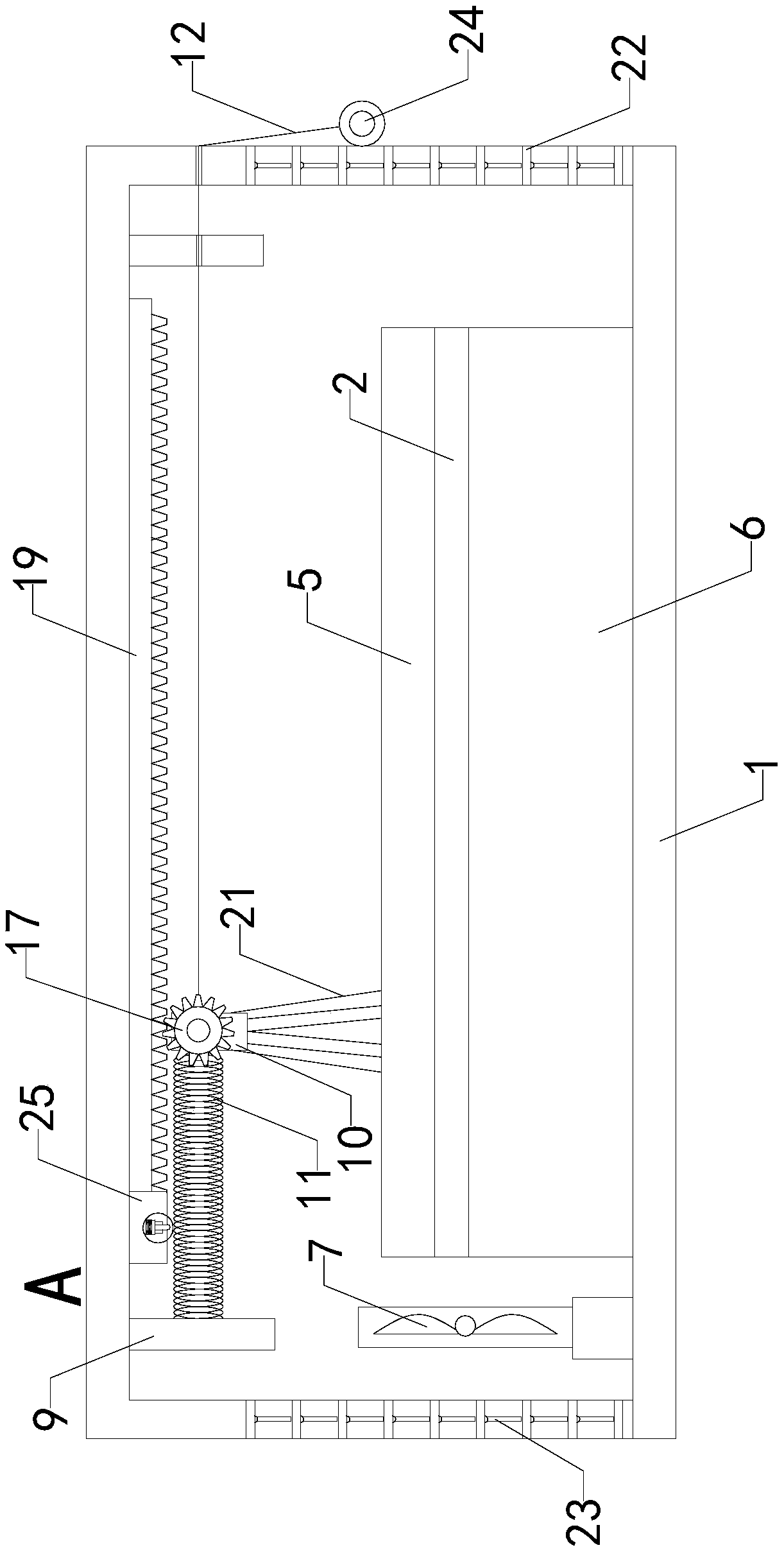
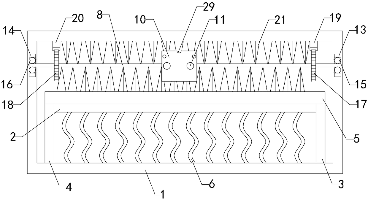
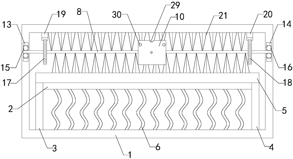
[0019] Such as Figure 1 to Figure 4 As shown, a kind of electronic chip cooling device of the present invention comprises casing 1, and the inside of casing 1 is provided with placement cavity; Multiple groups of cooling fins 6 and fans 7, the bottom ends of the front support plate 3 and the rear support plate 4 are respectively connected to the front and rear ends of the bottom wall of the cavity, and the top ends of the front support plate 3 and the rear support plate 4 are respectively connected to the bottom of the electronic chip 5. The heat-absorbing silica gel plate 2 is pasted on the bottom of the electronic chip 5, and multiple sets of cooling fins 6 are horizon...


PUM


Abstract

The invention relates to the technical field of heat dissipation auxiliary devices, in particular to an electronic chip heat dissipation device, which improves the heat dissipation effect, provides asuitable temperature environment for the operation of the electronic chip, ensures the service life of the electronic chip, improves the practicability, can clean dust attached to an electronic chip,and improves the reliability of usage. The electronic chip heat dissipation device comprises a casing, an endothermic silica gel plate, a front supporting plate, a rear supporting plate, an electronicchip, a plurality of sets of radiating fins, a fan, a rotating shaft, a left baffle plate, a right baffle plate, a connecting plate, a tension spring group, a traction line, a front ball bearing, a rear ball bearing, a front gear, a rear gear, a front rack, a rear rack and flexible bristles, wherein a placement cavity is formed in the casing, the left end of the casing is provided with an air inlet, the right end of the casing is provided with an air outlet, a front sliding groove is formed in the top part of the front side wall of the placement cavity, a rear sliding groove is formed in thetop part of the rear side wall of the placement cavity, a front sliding block is slidably mounted in the front sliding groove, and a rear sliding block is slidably mounted in the rear sliding groove.

Description

technical field [0001] The invention relates to the technical field of heat dissipation accessories, in particular to an electronic chip heat dissipation device. Background technique [0002] As everyone knows, the electronic chip cooling device is an auxiliary device used to dissipate heat when the electronic chip is working, and it has been widely used in the field of electronic device production and processing; the existing electronic chip cooling device includes a casing, a casing The interior of the housing is provided with a placement cavity, the bottom of the placement cavity is provided with a substrate, the top of the substrate is equipped with an electronic chip, and the left and right ends of the casing are provided with heat dissipation through holes; Dissipate the heat generated when the electronic chip is working; it is found in the use of the existing electronic chip cooling device that its heat dissipation effect is poor, and it is easy to accumulate heat in ...

Claims


Application Information

Patent Timeline
Patent Type & Authority Applications(China)
IPC IPC(8): H01L23/367H01L23/467H01L23/00
CPCH01L23/3672H01L23/467H01L23/564
Inventor 王昌华
Owner 盐城盈信通科技有限公司
Why Eureka
Try Eureka