Delay-based SDN multi-controller deployment method
What is AI technical title?
AI technical title is built by Patsnap AI team. It summarizes the technical point description of the patent document.
A multi-controller and controller technology, applied in the field of computer networks, can solve the problems of controller deployment and high cost, and achieve the effects of high utilization, minimal delay, and solving the problem of location deployment.
Active Publication Date: 2019-01-29
SICHUAN CHANGHONG ELECTRIC CO LTD
View PDF4 Cites 12 Cited by
Summary
Abstract
Description
Claims
Application Information
AI Technical Summary
This helps you quickly interpret patents by identifying the three key elements:
Problems solved by technology
Method used
Benefits of technology
Problems solved by technology
[0003] However, while SDN multi-controller deployment brings a series of benefits, it also brings a new problem, that is, the problem of controller deployment. In a given SDN network topology, how many controllers need to be placed, each Where should the controller be placed, and which switches should each controller manage
Different deployment locations of controllers have different impacts on network overhead, and the existing technologies pay attention to performance and ignore overhead, and have made leaps and bounds in small network deployments, but in large and even medium-sized network deployments However, it has great limitations. First, the cost is too high. Second, some areas are further optimized. Therefore, the existing controller deployment scheme still has great limitations.
Method used
Image
Click on the blue label to locate the original text in one second.
Reading with bidirectional positioning of images and text.
Examples
Embodiment 1
[0034] The technical solution disclosed in this embodiment is mainly to solve the problem of how to determine the number of controllers, deployment locations, and the number of controllers to be managed by each controller for a given SDN network topology in the deployment of SDN multi-controllers. switches to maximize the utilization of the network topology.
[0035] In order to specifically illustrate this technical solution, it is first necessary to introduce the multi-controller deployment solution in an ideal state, which is also a technical solution commonly used in the prior art:
[0036] The ideal multi-controller deployment scheme uses the average delay and the worst-case delay to measure the position deployment of multi-controllers. However, this rational approach ignores many delay processes, which is the current situation. There are the most common deficiencies of the prevailing technology;
[0037] Specifically, the calculation formula based on the average delay i...
Embodiment 2
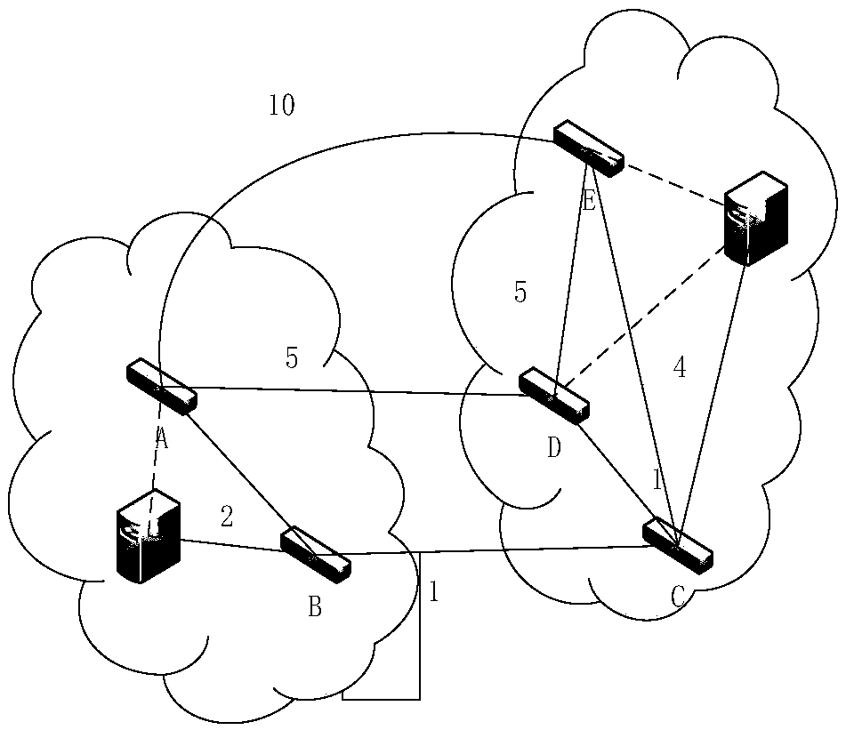
[0089] Such as image 3 As shown, applying the technical solution of the present invention, when there are multiple controllers in the network topology, each controller manages switches in a certain area, such as image 3 The 5 switches in the network can be divided into two areas. The switches in each area can only be controlled by one controller. There are five types of partitions, which are AB-CDE area, BC-ADE area, and CD-ABE area. District, BD-ACE District, CE-ABD District.
[0090] The optimal layout scheme in each control area is the same as the single controller layout scheme, and the steps are as follows:
[0091] S1. When the AB-CDE partition is used, the minimum average time delay scheme in the AB area and the minimum average time delay scheme in the CDE area are respectively obtained;
[0092] S2. Compute the minimum average time delay scheme by using the other four partitions in the same way as the first step;
[0093] S3. Compare the minimum average delays of ...
PUM
Abstract
The invention discloses a delay-based SDN multi-controller deployment method. According to the method, the delay and structure of network topology are analyzed; delay between each switch in the network and the degree of each node are calculated; the number of switches that can be deployed by each controller is determined, and a qualified node is selected according to a customization algorithm so as to be adopted as the deployment location of each controller, all switches in the management area of the controller are determined; a minimum average delay quantity and a worst case-oriented minimumdelay quantity are obtained according to a minimum average delay model and a worst case-oriented minimum delay model; then the same method is used to calculate a remaining qualified node, the remaining qualified node is adopted as the deployment position of another controller, so that a minimum average delay quantity and a worst case-oriented minimum delay quantity are obtained; and the above process is repeated until controller location deployment is completed. The method of the invention can be applied to algorithms for multi-controller location deployment of various network scales. With themethod adopted, a controller location deployment problem can be systematically solved.
Description
technical field [0001] The invention relates to the technical field of computer networks, in particular to a delay-based SDN network multi-controller deployment method. Background technique [0002] SDN creatively separates the control plane of the network device from the data forwarding function of the device, and completely concentrates the control function on the SDN controller. Different from the decentralized control of the traditional network, the centralized control of SDN enables the control plane to obtain the global information of network resources, so as to realize the optimization and allocation of resources according to the demand. At the same time, the centralized control of the network makes the network devices logically integrated, eliminating the need for on-site configuration and maintenance of each device, which greatly improves the convenience of network control and maintenance. In order to improve the performance and robustness of the network, the mecha...
Claims
Application Information
Patent Timeline
Application Date:The date an application was filed.
Publication Date:The date a patent or application was officially published.
First Publication Date:The earliest publication date of a patent with the same application number.
Issue Date:Publication date of the patent grant document.
PCT Entry Date:The Entry date of PCT National Phase.
Estimated Expiry Date:The statutory expiry date of a patent right according to the Patent Law, and it is the longest term of protection that the patent right can achieve without the termination of the patent right due to other reasons(Term extension factor has been taken into account ).
Invalid Date:Actual expiry date is based on effective date or publication date of legal transaction data of invalid patent.

