Metal lure and counter weight device
A counterweight device and submetallic technology, which is applied in the fields of artificial fishing bait, fishing, and application, can solve the problems of lack of characteristics and inflexible counterweight methods, and achieve simple processing technology, flexible counterweight methods, and convenient production. Effect
- Summary
- Abstract
- Description
- Claims
- Application Information
AI Technical Summary
Problems solved by technology
Method used
Image

Examples
Example Embodiment
[0048] Example one
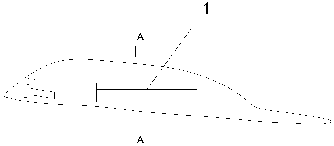
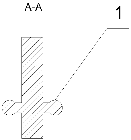
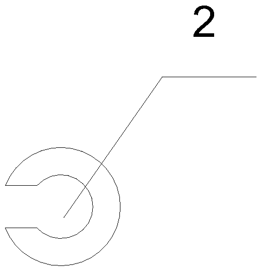
[0049] Such as Figure 1 to Figure 7 As shown, the new vibrating lure lure includes a fish-shaped body board with a counterweight fixing device, and the counterweight fixing device is movably connected to the counterweight device for fixing the counterweight device. The counterweight fixing device is a counterweight bolt 1, which is used to cooperate with the groove 2 on the counterweight device, such as Figure 3 to Figure 7 Shown are spherical, moon-shaped and diamond-shaped (fish-shaped) counterweight devices. The counterweight bolt 1 and the counterweight device can be an interference fit, so that the counterweight device can be firmly fixed on the counterweight bolt 1. There may also be a gap between the counterweight fixing device and the counterweight device, and there will be friction between the counterweight device and the fish-shaped body, causing noise. There are counterweight device fixing devices at both ends of the counterweight bolt 1 for fix...
Example Embodiment
[0050] Example two
[0051] Such as Picture 8 As shown, the difference from the first embodiment is that: one end of the counterweight device fixing device is a stopper 3 for blocking the counterweight device, and the other end is for passing through both sides of the fish-shaped body plate. Bolts and The nuts are fixed together, and it can also be fixed with double circles or pins. The bolt passes through the through hole 4, and then is screwed on the bolt with a nut for fixing. Alternatively, a double loop or pin can be buckled on the through hole 4 to fix the counterweight device. These are used to block the heavy metal to prevent it from slipping or fixing.
[0052] In addition, one end of the counterweight bolt on the fish-shaped body plate can be blocked by a block, and the other end is welded to prevent the counterweight metal from slipping or fixing.
Example Embodiment
[0053] Example three
[0054] Such as Figure 9 to Figure 11 As shown, the difference from the first embodiment is: the fish-shaped body has a metal strip fixing device for fixing the metal strip at the bottom of the abdomen, and the metal strip is used to pass through the counterweight on the counterweight device The holes enable the counterweight device to be fixed on the fish-shaped body plate. A second groove 5 is opened at the bottom of the abdomen of the fish-shaped body, and the metal strip fixing device is a fixing device located at both ends of the second groove 5. The metal bar fixing device is a bolt, and the metal bar is provided with collars on both sides, and the collar is sleeved on the screw body and then tightened with a nut. Such as Figure 15 to Figure 18 As shown, it is a counterweight device for connecting with the metal strip. The counterweight device has a groove for connecting with a multi-type strip, and the groove is a second through hole 6.
[0055] 11....
PUM
 Abstract
Description
Claims
Application Information
 - R&D
- Intellectual Property
- Life Sciences
- Materials
- Tech Scout
- Unparalleled Data Quality
- Higher Quality Content
- 60% Fewer Hallucinations
Browse by: Latest US Patents, China's latest patents, Technical Efficacy Thesaurus, Application Domain, Technology Topic, Popular Technical Reports.
© 2025 PatSnap. All rights reserved.Legal|Privacy policy|Modern Slavery Act Transparency Statement|Sitemap|About US| Contact US: help@patsnap.com