A feeding and clamping mechanism

A clamping mechanism and material feeding technology, which is applied in the field of mechanical devices, can solve the problems of large cumulative product error, low feeding quality and efficiency, and poor control of material tightness, so as to improve efficiency, avoid damage, and position precise effect

Active Publication Date: 2021-03-30
NINGBO HONGXIECHENG AUTO PARTS CO LTD
View PDF6 Cites 0 Cited by
  • Summary
  • Abstract
  • Description
  • Claims
  • Application Information

AI Technical Summary

Problems solved by technology

The existing feeders usually use two rollers to clamp the material or the cylinder to drive the material. The feeder with this structure can not control the tightness of the material well during the feeding, which will easily lead to the increase of the cumulative error of the product when stamping the product, and the feeding quality and quality. Efficiency is not high

Method used


Image

  • A feeding and clamping mechanism
  • A feeding and clamping mechanism
  • A feeding and clamping mechanism

Examples


Embodiment Construction

[0038]The following is a specific embodiment of the present invention and a further description of the technical solutions of the present invention, but the present invention is not limited to these embodiments.

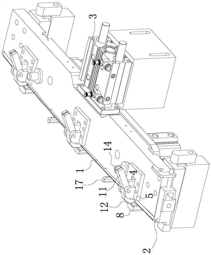
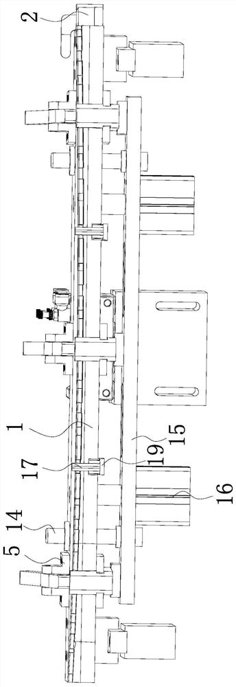
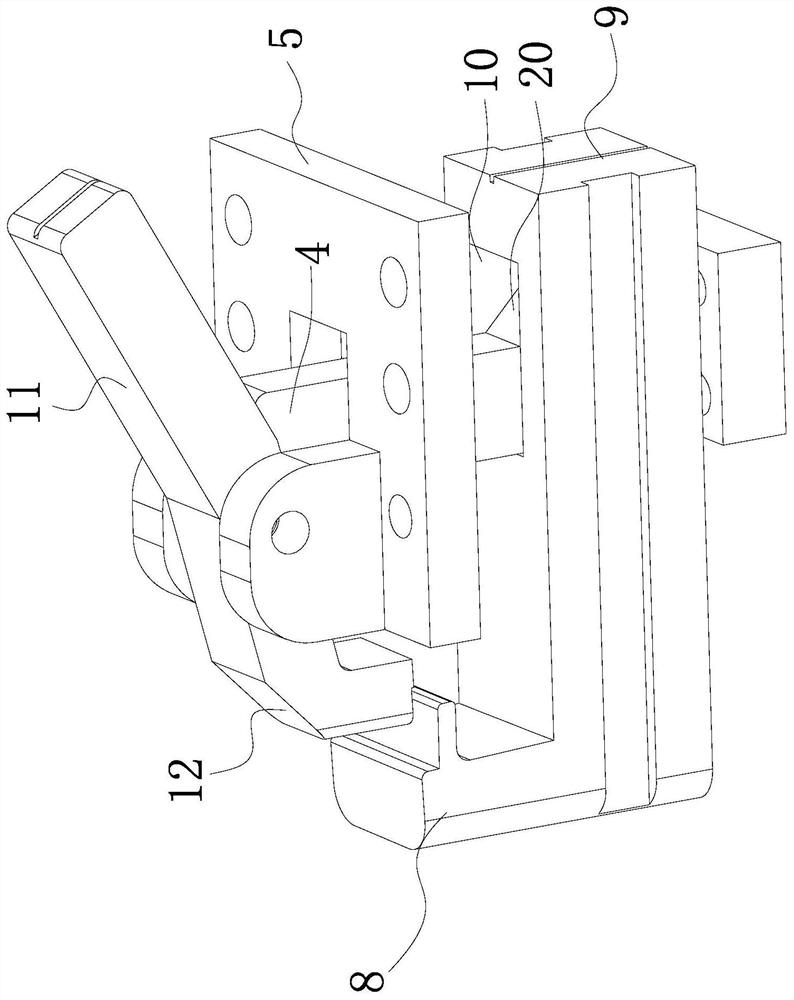
[0039]Such asFigure 1 to 6As shown, the feed clamping mechanism includes: a workpiece plate 1; end positioning assembly 2, which is disposed at the end of the workpiece plate 1; pre-clamping assembly, the activity is disposed on the workpiece plate 1; Lifting assembly, its activity is connected to the lower end of the workpiece plate 1; the workpiece fixing assembly is inserted on the workpiece plate 1 and its lower end is connected to the lifting assembly; when the lifting assembly rises, the workpiece fixing component can abut The side end and the upper end of the workpiece; push the cylinder 3, which is disposed on the side end of the workpiece plate 1, and the pushing the cylinder can be moved before and after moving the workpiece plate 1.

[0040]The workpiece placed plate ...


PUM


Abstract

The invention belongs to the field of mechanical devices, and provides a feeding and clamping mechanism. The mechanism comprises a workpiece putting plate, an end positioning assembly arranged on theend of the workpiece putting plate, a pre-clamping assembly movably arranged on the workpiece putting plate, a lifting assembly movably connected to the lower end of the workpiece putting plate, a workpiece fixing assembly inserted on the workpiece putting plate and a pushing air cylinder, the lower end of the workpiece fixing assembly is connected with the lifting assembly, when the lifting assembly ascends, the workpiece fixing assembly can abut against the side end and the upper end of a workpiece, and the pushing air cylinder is arranged on the side end of the workpiece putting plate and can drive the workpiece putting plate to move front and back. Compared with the prior art, the mechanism has the beneficial effects that the workpiece fixing assembly can clamp the side face and the upper face of the product, position precision of a product in the conveying process can be ensured, when the lifting air cylinder ascends, a transverse fixed plate and a longitudinal fixed plate can bedriven at the same time to move, the workpiece clamping efficiency is improved, and the structure cost is reduced.

Description

Technical field[0001]The present invention belongs to the field of machinery, and more particularly to a feed clamping mechanism.Background technique[0002]With the development of manufacturing technology, especially the flourishing industry, it is increasingly required stamping equipment with high efficiency, high precision, and high automation. The punch is a common stamping production equipment. When the previous production, the feed is usually used artificial feed mode, causing high safety production rates. To this end, people have designed a variety of forms of feeders to replace artificial punching, by This improves the safety of production.[0003]The feeder is an important accessory device that is important, and the accuracy of the product position can directly affect the stability and efficiency of the stamping machine operation. The existing feeder is multi-two roller clamping or cylinder-driven feed. The feeder of this structure is easy to control the tight of the material w...

Claims


Application Information

Patent Timeline
Patent Type & Authority Patents(China)
IPC IPC(8): B21D43/10
CPCB21D43/10
Inventor 王良杰刘玉权
Owner NINGBO HONGXIECHENG AUTO PARTS CO LTD
Why Eureka
Try Eureka