Punching device for full-automatic punching machine

A punching device and punching machine technology, applied in metal processing and other directions, can solve the problems of unsteady clamping of workpieces, unfavorable production and use, workpiece position deviation, etc. solid effect

Inactive Publication Date: 2019-02-01
邵帅
View PDF7 Cites 3 Cited by
  • Summary
  • Abstract
  • Description
  • Claims
  • Application Information

AI Technical Summary

Problems solved by technology

[0004] However, most of the punching mechanisms of the existing fully automatic punching machines cannot firmly hold the workpiece during the punching operation, so that the workpiece is prone to position deviation during the punching process, resulting in a deviation in the punching position, increasing the The defective rate is not conducive to production and use, so we propose a punching device for a fully automatic punching machine to solve the above problems

Method used


Image

  • Punching device for full-automatic punching machine
  • Punching device for full-automatic punching machine
  • Punching device for full-automatic punching machine

Examples


Embodiment

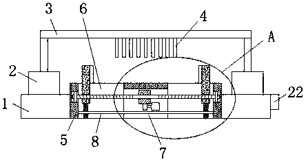
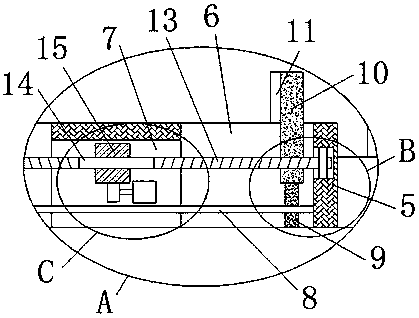
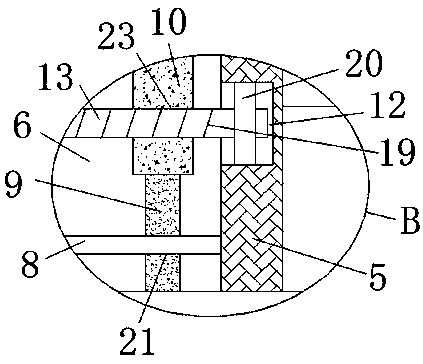
[0026] reference Figure 1-5 In this embodiment, a punching device for a fully automatic punching machine is proposed, which includes a frame 1, a hydraulic cylinder 2 is fixedly installed on the top of the frame 1, and the output shafts of two hydraulic cylinders 2 are fixedly installed There is the same punching table 3, the bottom of the punching table 3 is fixedly installed with a plurality of punching rods 4, the frame 1 is provided with a workbench 5, and the top of the workbench 5 is provided with rectangular holes 6 on both sides, and two The inner wall of the two rectangular holes 6 close to each other is provided with the same mounting hole 7, and the bottom of the mounting hole 7 is set as an opening. The inner wall of the two rectangular holes 6 away from each other is welded with the same guide rod 8. The outer sliding sleeve of 8 has two positioning plates 9, and the two positioning plates 9 are respectively slidably installed in two rectangular holes 6. The inner...


PUM


Abstract

The invention discloses a punching device for a full-automatic punching machine. The punching device comprises a rack. Hydraulic cylinders are fixedly installed on the top of the rack. The same punching table is fixedly installed on output shafts of the two hydraulic cylinders. Multiple punching rods are fixedly installed on the bottom of the punching table. The rack is provided with a working table. Rectangular holes are formed in the two sides of the top of the working table correspondingly. The same installing hole is formed in the inner walls of the sides, close to each other, of the two rectangular holes. An opening is formed in the bottom of the installing hole. The same guide rod is welded to the inner walls of the sides, away from each other, of the two rectangular holes. The outerside of the guide rod is sleeved with two locating plates in a sliding manner. The punching device is reasonable in design, high in practicality and convenient to control, two screw rods are driven to rotate conveniently at the same time, two clamping plates move in the direction close to each other, thus workpieces can be clamped to the working table stably, the situation that positions of the workpieces deviate in the punching operation process is effectively avoided, and the rejection rate is reduced.

Description

Technical field [0001] The invention relates to the technical field of punching machines, and in particular to a punching device for a fully automatic punching machine. Background technique [0002] Automatic punching machine, commonly used for punching circuit boards, circuit boards, printed boards, film boards and membrane switches. It generally includes a manipulator, a loading platform, a punching platform, and an unloading platform to complete the loading of the workpiece in sequence. Material, punching and blanking operations. Therefore, the existing fully automatic punching machine generally adopts the loading platform, the punching platform and the unloading platform to be arranged in a row, and then through multiple single-arm manipulators, the workpiece is sequentially moved from the previous work platform Transfer to the next work platform to complete the loading, punching and unloading operations of the workpiece in sequence. [0003] After searching, the patent docum...

Claims


Application Information

Patent Timeline
Patent Type & Authority Applications(China)
IPC IPC(8): B26F1/14B26D5/08B26D7/01
CPCB26D5/08B26D7/01B26F1/14
Inventor 戚丹丹
Owner 邵帅
Why Eureka
Try Eureka