Supercharge Your Innovation With Domain-Expert AI Agents!

Die taking device for plastic die

A plastic mold and mounting plate technology, applied in the field of plastic molds, can solve the problems of mold damage and low mold taking efficiency, and achieve the effect of simple structure and high mold taking efficiency

Inactive Publication Date: 2019-02-01
HUANGSHI ZHONGJIE MOLD
View PDF0 Cites 0 Cited by
  • Summary
  • Abstract
  • Description
  • Claims
  • Application Information

AI Technical Summary

Problems solved by technology

[0003] The purpose of the present invention is to solve the shortcomings of low mold taking efficiency and easy to cause mold damage in the prior art, and propose a mold taking device for plastic molds

Method used


Image

  • Die taking device for plastic die
  • Die taking device for plastic die

Examples


Embodiment Construction

[0013] The following will clearly and completely describe the technical solutions in the embodiments of the present invention with reference to the accompanying drawings in the embodiments of the present invention. Obviously, the described embodiments are only some, not all, embodiments of the present invention.

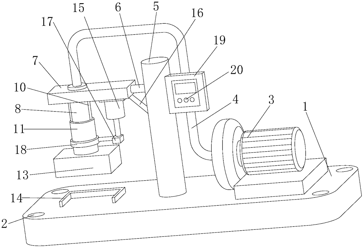
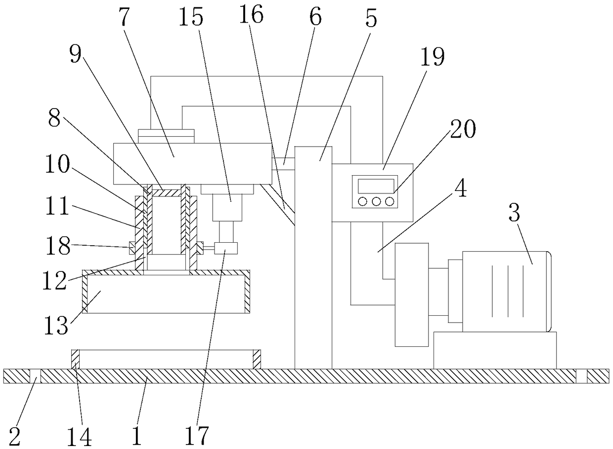
[0014] refer to Figure 1-2 , a mold taking device for plastic molds, comprising a mounting plate 1, mounting holes 2 are provided at the four corners of the mounting plate 1, the function of the mounting holes 2 is to facilitate fixing the mounting plate 1, and one side of the upper surface of the mounting plate 1 is fixed An air suction pump 3 is provided, and the function of the air suction pump 3 is to generate suction force to suck out the mould. One side of the air suction pump 3 is fixedly connected with an air guide tube 4, and the side of the air suction pump 3 on the mounting plate 1 is fixedly connected with a Support rod 5, one side of the upper end of su...


PUM


Abstract

The invention relates to the technical field of plastic dies, and particularly relates to a die taking device for a plastic die. The die taking device for the plastic die comprises an installation plate, wherein an air suction pump is fixedly arranged at one side of the upper surface of the installation plate; an air guide pipe is fixedly connected to one side of the air suction pump; a support rod is fixedly connected to the installation plate and to one side of the air suction pump; a connection rod is fixedly connected to one side of the upper end of the support rod; a first fixed plate isfixedly connected to one end away from the support rod, of the connection rod; a connection pipe is arranged on the first fixed plate; the top end of the connection pipe is fixedly connected with theair guide pipe; a movable pipe is movably connected to the outer side of the connection pipe; a cover body is fixedly connected to the bottom end of the movable pipe; a connection frame is fixedly connected to the movable pipe; a telescopic cylinder is fixedly connected to the lower surface of the first fixed plate and to one side of the movable pipe through a fixed seat; a connection block is fixedly connected to the telescopic end of the telescopic cylinder; and a controller is fixedly arranged on a second fixed plate. The die taking device for the plastic die is simple in structure and worthy of popularization.

Description

technical field [0001] The invention relates to the technical field of plastic molds, in particular to a mold taking device for plastic molds. Background technique [0002] After the mold is poured and formed, the formwork is opened, and most of the molds will be stuck on the lower formwork, especially when pouring some smaller molds. In the prior art, most of the molds are taken manually, resulting in high labor intensity and low efficiency of mold taking , easily lead to mold damage. Contents of the invention [0003] The object of the present invention is to solve the shortcomings of low mold taking efficiency and easy mold damage in the prior art, and propose a mold taking device for plastic molds. [0004] In order to achieve the above object, the present invention adopts the following technical solutions: [0005] Design a mold taking device for plastic molds, including a mounting plate, one side of the upper surface of the mounting plate is fixedly provided with a...

Claims


Application Information

Patent Timeline
Patent Type & Authority Applications(China)
IPC IPC(8): B29C33/30
CPCB29C33/30
Inventor 朱积平
Owner HUANGSHI ZHONGJIE MOLD
Features
  • R&D
  • Intellectual Property
  • Life Sciences
  • Materials
  • Tech Scout
  • Unparalleled Data Quality
  • Higher Quality Content
  • 60% Fewer Hallucinations
Learn More