Anchor tension plate type anchoring structure cable and tensioning construction method thereof

A technology of anchoring structure and anchoring plate, which is applied to bridge parts, erecting/assembling bridges, bridges, etc., can solve the problems such as the inability to adjust the tension of the pinned cable structure, the inconvenient tension operation, and the weakening of the box girder structure. , to achieve the effect of compact structure, not easy to accumulate water and rust, and good integrity

Pending Publication Date: 2019-02-01
LIUZHOU OVM MASCH CO LTD
View PDF10 Cites 5 Cited by
  • Summary
  • Abstract
  • Description
  • Claims
  • Application Information

AI Technical Summary

Problems solved by technology

[0002] The connection method between the bridge stay cable and the stiffened beam can generally adopt the anchor head pressure-bearing type (such as Figure 17 shown) or pin-on (as Figure 18-1~Figure 18-2 As shown), when the conventional anchor head is anchored at the bottom of the stiffened beam under pressure, it is necessary to make a special hanging basket-type tension platform and install tension under the beam; while when anchoring in the middle of the steel box girder, the design of the

Method used


Image

  • Anchor tension plate type anchoring structure cable and tensioning construction method thereof
  • Anchor tension plate type anchoring structure cable and tensioning construction method thereof
  • Anchor tension plate type anchoring structure cable and tensioning construction method thereof

Examples


Embodiment 1

[0107] A kind of anchor pull plate type anchoring structure cable and its tension construction method with reaction force structure ear plate I of reaction force structure:

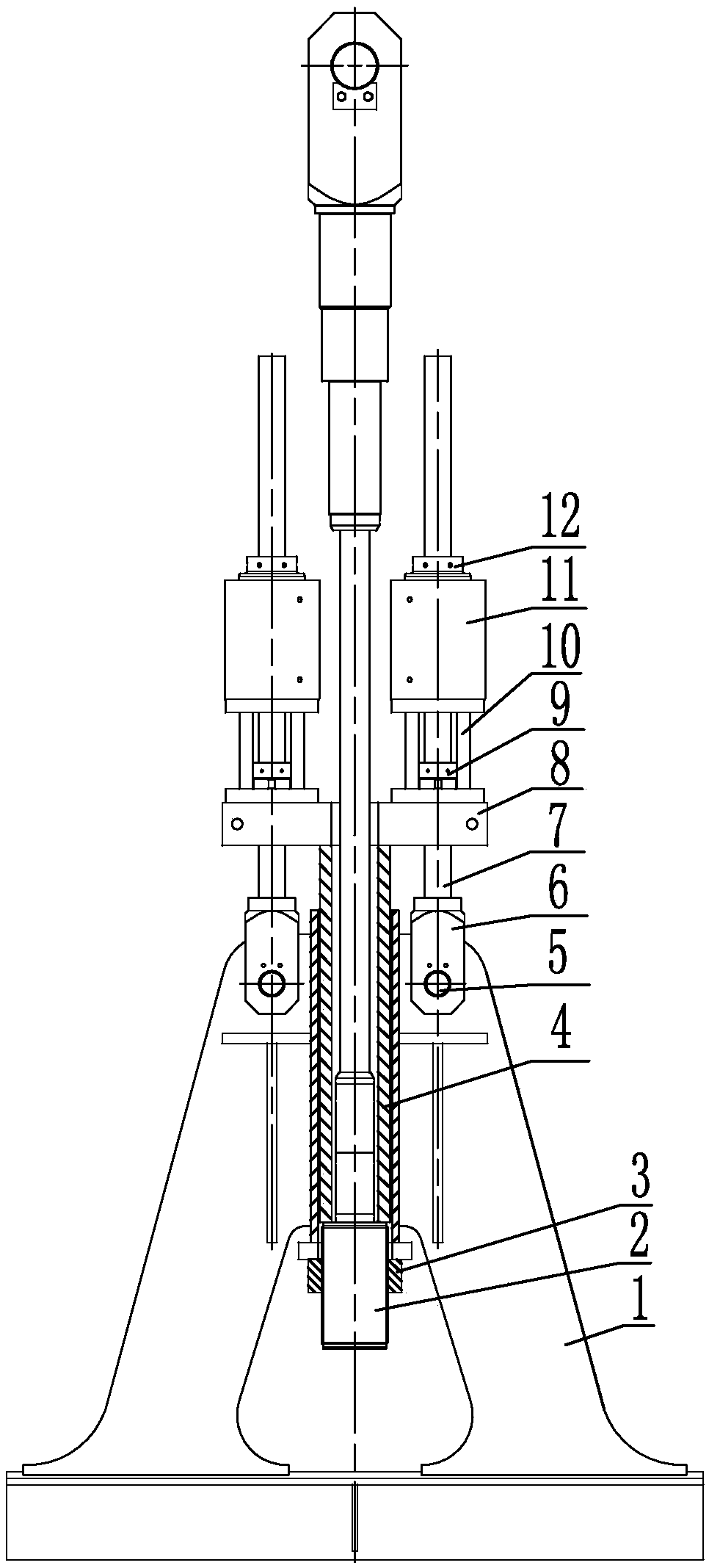
[0108] Such as Figure 1-1~Figure 1-2 As shown, the anchor plate type anchor structure cable with the anti-force structure ear plate I includes the anchor plate I1a with the anti-force structure, the cable anchor 2, the anchor nut 3 and the tension mechanism;

[0109] The anchor plate I1a with reaction force structure includes a bridge deck 101, two anchor plate main plates I 102a, an anchor backing plate 103, a steel pipe I 104a, an anchor plate sealing plate 105, a reinforcing rib plate 106, and a steel pipe I 104a Located in the middle of the two anchor plate main plates I 102a, the two anchor plate main plates I are fixedly connected into a whole, the anchor pad 103 with an anchor hole in the middle is fixed at the bottom of the steel pipe I 104a, and the anchor hole axis of the anchor pad 103 is connected ...

Embodiment 2

[0127] One kind of reaction force structure is a steel pipe reaction force integrated step or a threaded steel pipe and nut combined step anchor pull plate type anchor structure cable:

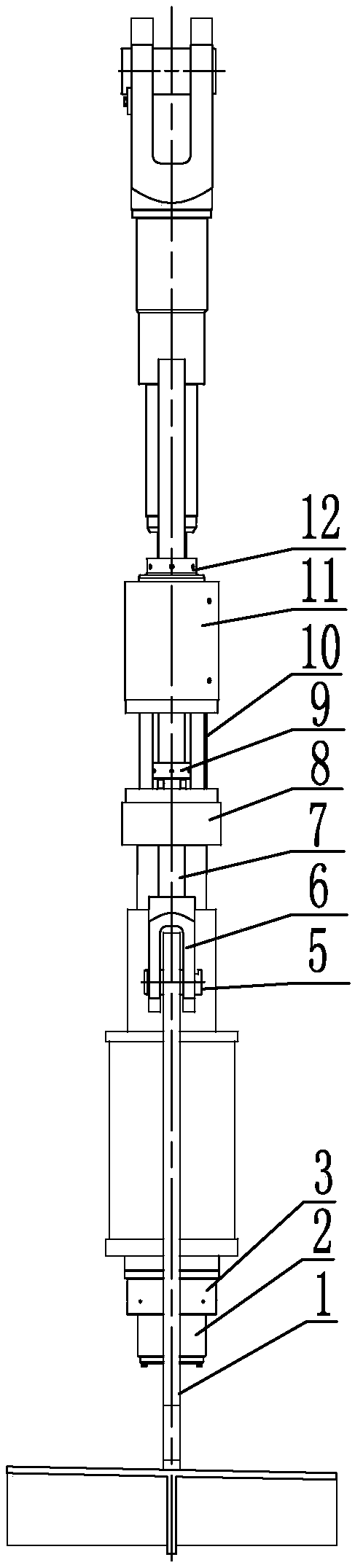
[0128] Such as Figure 2-1~Figure 2-2 As shown, the reaction force structure is a steel pipe reaction force integrated step or a threaded steel pipe and nut combined step anchor pull plate type anchor structure. The pull cable anchor pull plate type anchor structure. The pull cable includes an anchor pull with a reaction force structure. Plate II1b, cable anchor 2, anchor nut 3 and tension mechanism;

[0129] The anchor plate II 1b with reaction force structure includes bridge deck 101, two anchor plate main boards II 102b, anchor pad 103, steel pipe II 104b, anchor plate sealing plate 105 and stiffener plate 106, steel pipe Ⅱ104b is located in the middle of the two anchor plate main plates Ⅱ102b. The two anchor plate main plates Ⅱ are fixedly connected into a whole. The anchor pad 103 with an anch...

Embodiment 3

[0150] A kind of anchor pull plate type anchoring structure cable with anti-force structure ear plate II and its tension construction method:

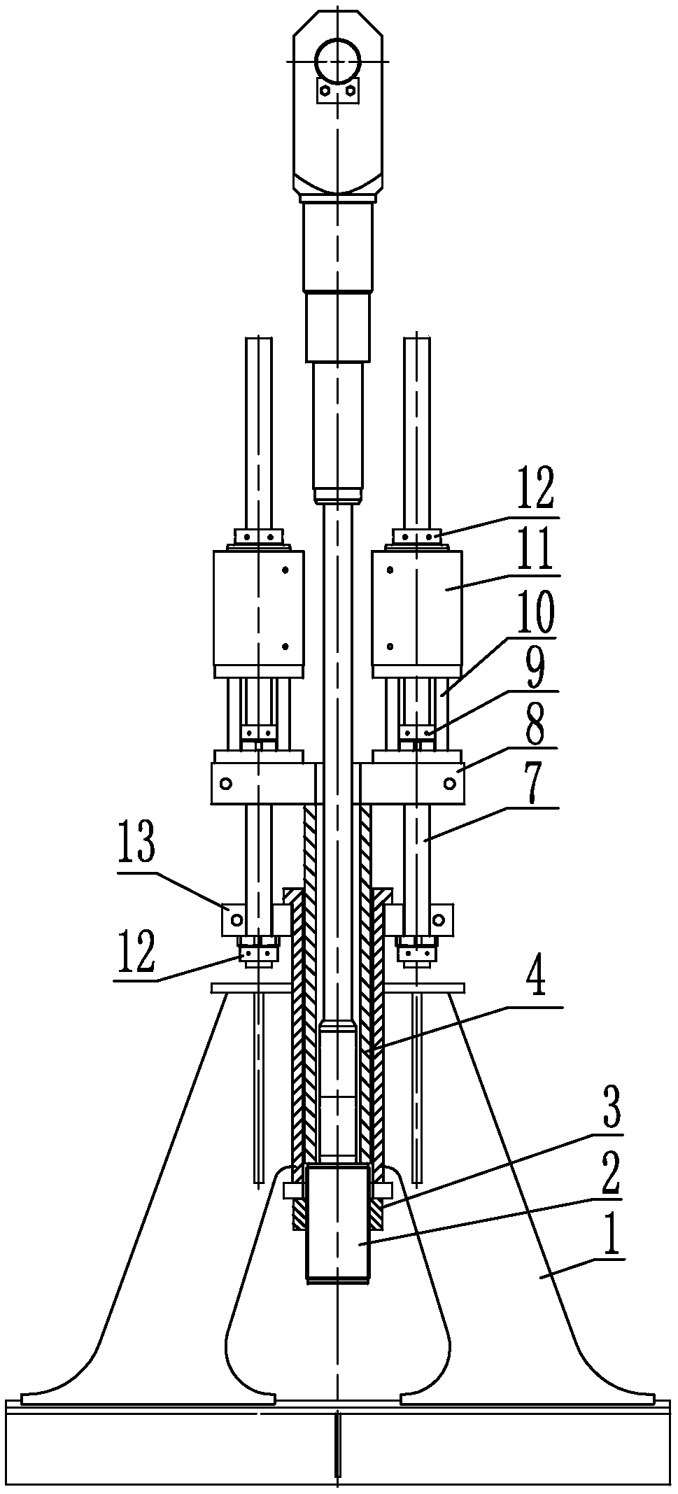
[0151] Such as Figure 10-1~Figure 10-2 As shown, the basic structure of the anchor plate type anchoring structure cable whose reaction force structure is a reaction force structure lug plate is the same as the first embodiment, and the difference from the first embodiment is:

[0152] The anchor plate 1 of the anchor plate type anchor structure cable is an anchor plate III 1c with a reaction force structure. The anchor plate III 1c with a reaction force structure includes a bridge deck 101, two anchor plate main plates II 102b, The anchor pad 103, the steel pipe I 104a, the anchor plate sealing plate 105 and the reinforcing rib plate 106, the steel pipe I 104a is located in the middle of the two anchor plate main plates II 102b, and the two anchor plate main plates II are fixedly connected into a whole. The anchor plate 103 of the anchor h...


PUM


Abstract

An anchor tension plate type anchoring structure cable comprises an anchor tension plate with a counter-force structure, a cable anchorage device, an anchoring nut and a tensioning mechanism. The anchor tension plate comprises a bridge deck, anchor tension plate main plates, an anchor backing plate, steel ducts and an anchor tension plate upper sealing plate. The anchor tension plate main plates are symmetrically fixed on the bridge deck to form an invert "V" shape, the steel ducts are positioned between the two anchor tension plate main plates to fixedly connect the two anchor tension plate main plates into a whole, and the anchor tension plate upper sealing plate is positioned at the middles or the tops of the anchor tension plate main plates; the anchor backing plate is fixed at the bottoms of the steel ducts, and the steel ducts protrude out of the anchor tension plate upper sealing plate; the counter-force structure is a counter-force structure lug plate located on the upper partsof the anchor tension plate main plates or an integral counter-force step structure arranged on the steel ducts of the anchor tension plate. In the installation state, the bridge deck at the lower end of the anchor tension plate is fixed on a deck, and the lower end of the cable penetrates into the steel ducts of the anchor tension plate; the tensioning mechanism is installed on the counter-forcestructure arranged on the upper part of the anchor tension plate. By using the structure cable and the tensioning construction method, the tensioning construction of the cable can be carried out on the deck.

Description

Technical field [0001] The invention relates to a bridge cable and a construction method thereof, in particular to an anchor pull plate type anchor structure cable and a tension construction method thereof. Background technique [0002] The connection method of the bridge cable and the stiffening beam can generally adopt the anchor head pressure type (such as Figure 17 Shown) or pin-connected (such as Figure 18-1~Figure 18-2 (Shown), when the conventional anchor head pressure-bearing anchoring is at the bottom of the stiffening beam, a special hanging basket-type tension platform needs to be made, and the tensioning platform is installed under the beam; and when the anchor is anchored in the middle of the steel box beam, in the design of the box beam It is necessary to reserve enough space for tensioning, so the box girder structure is easily weakened, and the tensioning operation in a narrow space is very inconvenient; the pin connection type uses a pin to connect the lower end ...

Claims


Application Information

Patent Timeline
IPC IPC(8): E01D19/16E01D21/00
CPCE01D19/16E01D21/00Y02A30/30
Inventor 邵长宇彭春阳谢正元陈亮周伟翔黄家珍韦福堂朱元苏韩黄子能李启富雷欢
Owner LIUZHOU OVM MASCH CO LTD
Why Eureka
Try Eureka