power protection circuit

A power protection and circuit technology, which is applied in the field of crosstalk-proof power protection circuits, can solve problems such as false triggering of the protection circuit 1, exceeding the safety range, and increased leakage current, so as to avoid false triggering, improve reliability, and design flexibly Effect

Active Publication Date: 2020-11-27
DIOO MICROCIRCUITS CO LTD
View PDF6 Cites 0 Cited by
  • Summary
  • Abstract
  • Description
  • Claims
  • Application Information

AI Technical Summary

Problems solved by technology

However, when the power grid has large disturbance fluctuations or the main power system switches and there is a large surge, the main channel of the node VBUS+ will couple into a peak voltage with a narrow pulse width, causing the protection circuit 1 of the prior art to malfunction. Triggered, causing a misjudgment, and turning on the switch tube M that should not be turned on. At this time, the leakage current will increase sharply and exceed the safe range, causing the danger of electric shock to the user.
[0004] Therefore, how to provide a low-cost power supply protection circuit that can avoid electric shock hazards to users due to misjudgment is an urgent problem to be solved by various businesses.

Method used


Image

  • power protection circuit
  • power protection circuit
  • power protection circuit

Examples


Embodiment Construction

[0040] The implementation of the present invention is described below with specific examples, and those skilled in the art can easily understand other advantages and effects of the present invention from the content disclosed in this specification. The present invention can also be implemented or applied through other different specific embodiments.

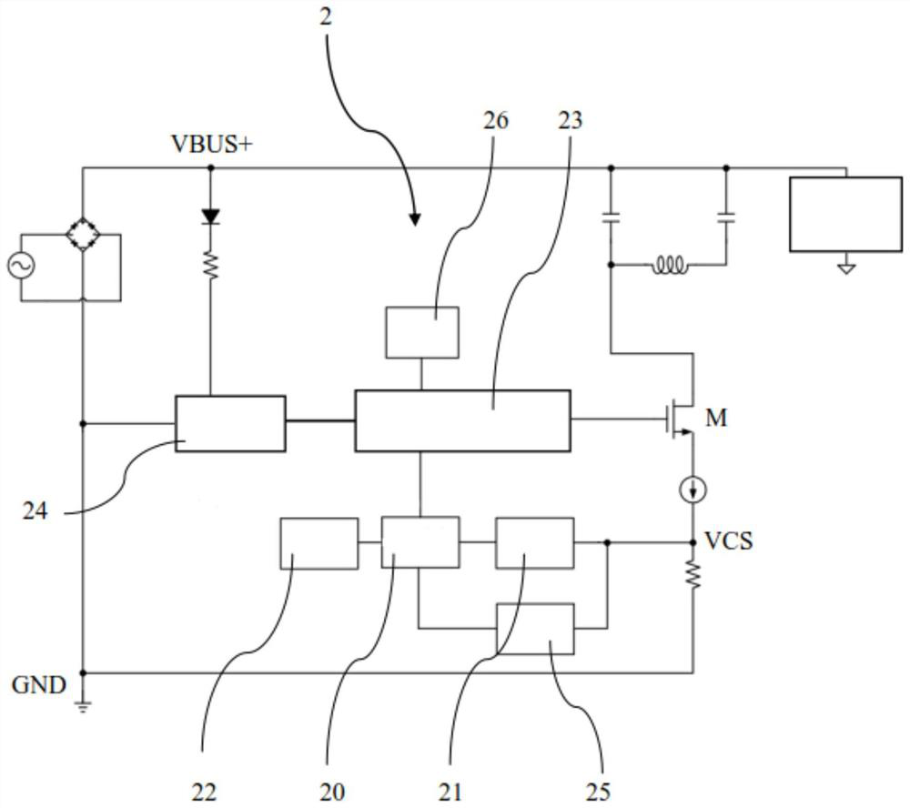
[0041] see figure 2 , figure 2 It is a schematic diagram of the structure of the power supply protection circuit according to the first embodiment of the present invention. As shown in the figure, the power protection circuit 2 of the present invention includes a pulse generation module 20 , an impedance detection module 21 and a time mask module 22 .

[0042] The pulse generating module 20 is used to generate a pulse signal to control the turn-on or turn-off of a switch M. For example, when the pulse signal is at a high level, the switch M is turned on instantaneously. Wherein, when the pulse signal makes the switch M turn ...


PUM


Abstract

A power supply protection circuit, comprising a pulse-generating module, an impedance-detecting module, and a time-mask module. The pulse generating module is used to generate a pulse signal so as to control on and off of a switch transistor, wherein the switch transistor generates a voltage signal when the pulse signal turns on the switch transistor; the impedance detecting module is connected to the pulse generating module and the switch transistor so as to detect whether the voltage of the voltage signal is greater than a set voltage threshold; if yes, the impedance detecting module generates a time detecting signal; and the time-mask module is connected to the impedance detecting module and the switch transistor so as to determine whether the holding time of the time detecting signal is greater than a set time threshold; if yes, the time-mask module generates an on signal to turn on the switch transistor; and if no, the time-mask module generates an off signal to turn off the switch transistor.

Description

technical field [0001] The invention relates to a power supply protection circuit, in particular to a crosstalk-proof power supply protection circuit. Background technique [0002] In the existing power system, one of the common power system circuit architectures is to install the input voltage terminals on different positions of the power board. For such a circuit architecture, when one end of the power system is connected to the power grid, the other end When floating, it will be charged through the internal circuit. This situation will cause serious problems. If the user does not distinguish clearly whether the power supply has been cut off when installing the power system of this structure, and if one end of the power system of this structure is connected to the grid, the other end suspended in the air will be charged and may cause The user who touches it will get an electric shock. [0003] There are two main methods to solve the above problems in the prior art, one o...

Claims


Application Information

Patent Timeline
Patent Type & Authority Patents(China)
IPC IPC(8): H02H3/00H02H3/20H02H3/10H02H5/04
CPCH02H3/00H02H3/10H02H3/20H02H5/04
Inventor 庄华龙曹磊
Owner DIOO MICROCIRCUITS CO LTD
Why Eureka
Try Eureka