Current triggering type detonation integrated circuit applied to electronic safety system

An electronic security and integrated circuit technology, which is applied in blasting and other directions, can solve the problems of peripheral circuit interference, circuit complexity, narrow time width of detection and triggering methods, etc., and achieve the effect of avoiding false triggering problems

Active Publication Date: 2022-01-14
BEIJING INSTITUTE OF TECHNOLOGYGY
View PDF12 Cites 0 Cited by
  • Summary
  • Abstract
  • Description
  • Claims
  • Application Information

AI Technical Summary

Problems solved by technology

[0003] All of the above trigger methods have requirements for instantaneousness, so the time width of the detection trigger method is narrow, which makes the trigger method more susceptible to interference from transient signals
The first logic level is most susceptible to interference
The second high-voltage trigger signal requires an external high-voltage signal, which leads to complex circuits and the high-voltage boost process will also interfere with peripheral circuits.
The disadvantage of the differential trigger method is that the generation of differential signals is also realized by logic levels.
Although the differential itself can improve the anti-interference ability, the logic level of the previous stage will still be affected by the interference

Method used


Image

  • Current triggering type detonation integrated circuit applied to electronic safety system
  • Current triggering type detonation integrated circuit applied to electronic safety system
  • Current triggering type detonation integrated circuit applied to electronic safety system

Examples


Embodiment Construction

[0018] The technical solutions of the present invention will be clearly and completely described below in conjunction with the accompanying drawings. Apparently, the described embodiments are some of the embodiments of the present invention, but not all of them. Based on the embodiments of the present invention, all other embodiments obtained by persons of ordinary skill in the art without making creative efforts belong to the protection scope of the present invention.

[0019] In the description of the present invention, it should be noted that the terms "center", "upper", "lower", "left", "right", "vertical", "horizontal", "inner", "outer" etc. The indicated orientation or positional relationship is based on the orientation or positional relationship shown in the drawings, and is only for the convenience of describing the present invention and simplifying the description, rather than indicating or implying that the referred device or element must have a specific orientation, ...


PUM


Abstract

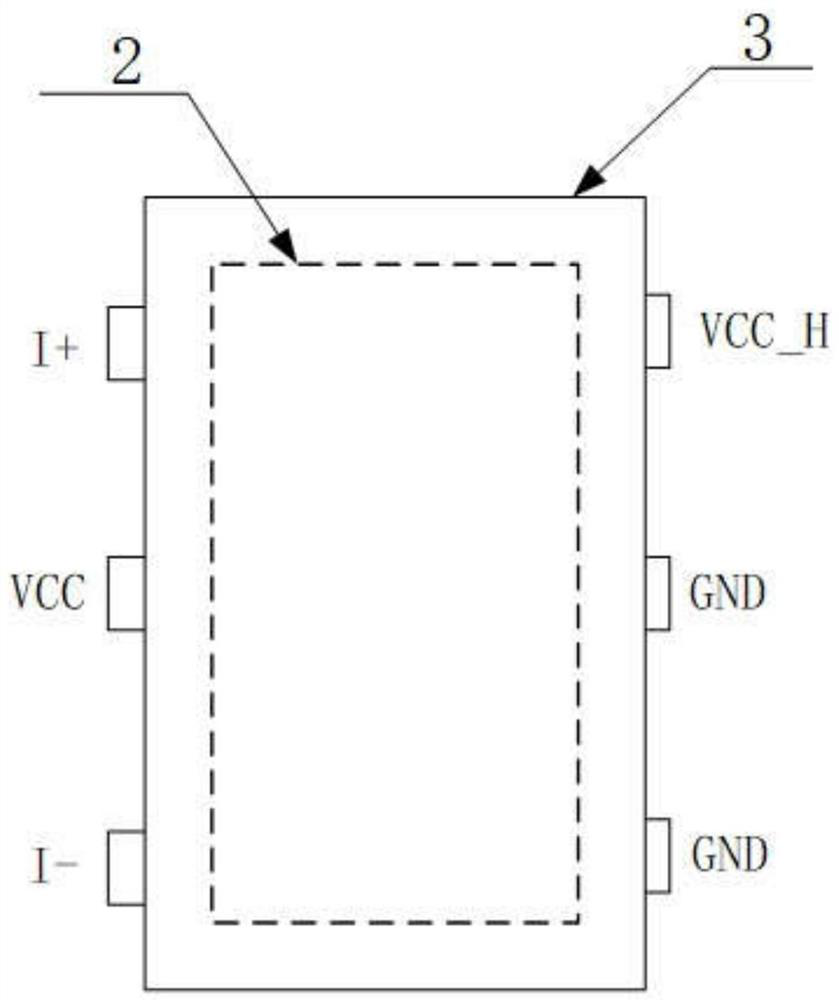
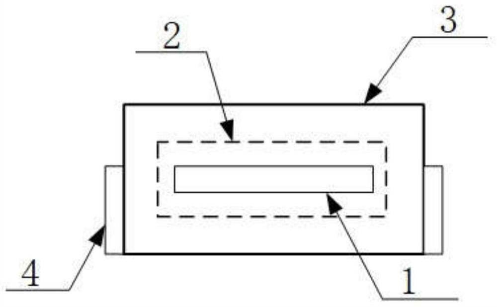
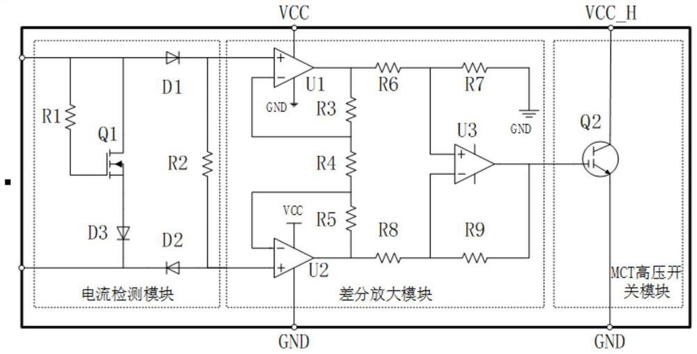
The invention provides a current triggering type detonation integrated circuit applied to an electronic safety system. The current triggering type detonation integrated circuit comprises a PCB substrate circuit, an internal insulation packaging layer surrounding the PCB substrate circuit, an external metal shielding layer and an external lead layer. The external lead layer is connected with pins of the internal PCB substrate circuit, and the pins comprise a current anode input end I +, a current cathode output end I-, a power supply pin VCC, a grounding pin GND and a high-voltage end VCCH; the PCB substrate circuit is integrated with a current detection module, a differential amplification module, a high-voltage switch module, a current positive electrode end, a current negative electrode end and a high-voltage end. According to a packaging method, the influence of direct external interference on the internal circuit can be greatly reduced; and compared with a detonation circuit triggered by a level, the detonation circuit provided by the invention has the advantages that a current-triggered detonating mode is realized; and when the voltage of the current positive electrode end and the voltage of the current negative electrode end are voltage signals, the detonation circuit does not detonate, and the problem of false triggering caused by externally input interference level is avoided.

Description

technical field [0001] The invention relates to the technical field of detonation circuits in electronic safety systems, in particular to a current-triggered detonation integrated circuit applied to electronic safety systems. Background technique [0002] The detonation circuit of the existing electronic safety system mainly has three trigger modes: the first one is logic level voltage trigger, and there are two trigger modes of positive logic level or negative logic level. The second is high-voltage level triggering. The third is the differential voltage trigger mode. [0003] All of the trigger methods above have requirements for instantaneousness, so the time width for detecting trigger methods is narrow, which makes the trigger methods more susceptible to interference from transient signals. The first logic level is the most susceptible to interference. The second high-voltage trigger signal requires an external high-voltage signal, which makes the circuit complex and...

Claims


Application Information

Patent Timeline
Patent Type & Authority Applications(China)
IPC IPC(8): F42D1/05
CPCF42D1/05
Inventor 杨成伟吴薛勇毛瑞芝程新亚杨银芳刘畅李杰
Owner BEIJING INSTITUTE OF TECHNOLOGYGY
Why Eureka
Try Eureka