Synchronous trigger device with multi-stage digital delay function and trigger method

A technology of synchronous triggering and digital delay, applied in the direction of measuring devices, digital variable display, digital variable/waveform display, etc., can solve the problem of reducing the trigger success rate, not having the function of synchronous trigger signal output hold, high-speed comparator output level Jumping back and forth and other issues to achieve the effect of improving the receiving frequency range and friendly human-computer interaction interface

Active Publication Date: 2019-08-09
XI AN JIAOTONG UNIV
View PDF11 Cites 0 Cited by
  • Summary
  • Abstract
  • Description
  • Claims
  • Application Information

AI Technical Summary

Problems solved by technology

During the operation of the substation switch, the arcing time can exceed 1s, but limited by the memory depth of the oscilloscope, the existing synchronous trigger device usually cannot capture the complete arc discharge waveform at a high sampling rate after completing a trigger; at the same time, it does not have a synchronous trigger signal output hold function
If the electromagnetic wave signal received by the existing synchronous trigger device is near the set trigger threshold, the output level of the high-speed comparator is likely to jump back and forth, resulting in unstable output of the trigger signal and reducing the trigger success rate

Method used


Image

  • Synchronous trigger device with multi-stage digital delay function and trigger method
  • Synchronous trigger device with multi-stage digital delay function and trigger method
  • Synchronous trigger device with multi-stage digital delay function and trigger method

Examples


Embodiment Construction

[0051] The present invention will be further described in detail below in conjunction with the accompanying drawings, which are explanations rather than limitations of the present invention.

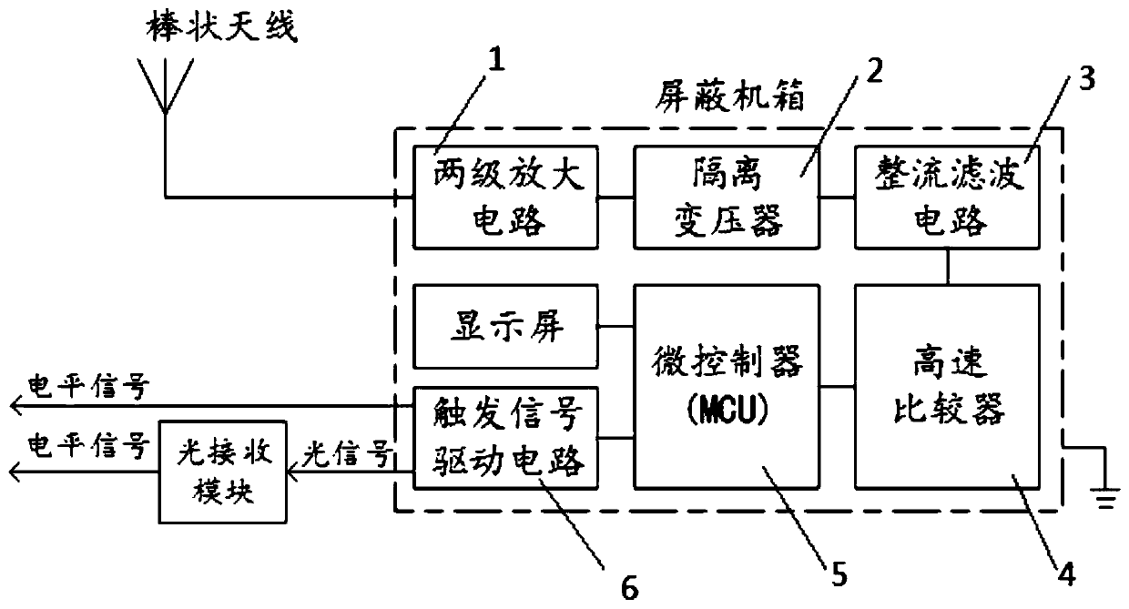
[0052] Please refer to figure 1 , a synchronous trigger device with multi-stage digital delay function, comprising an electromagnetic wave synchronous trigger device and a light receiving module used in conjunction with it.

[0053] Among them, the electromagnetic wave synchronous trigger instrument is processed by aluminum shielding shell, and the internal setting is used to realize the electromagnetic wave receiving, comparing and synchronous signal output in one circuit board and rechargeable battery, and the external setting is used to complete the touch display screen of human-computer interaction and necessary peripheral devices.

[0054] The optical receiving module is used to receive the optical signal of the electromagnetic wave synchronous trigger instrument, and convert the o...


PUM


Abstract

The invention discloses a synchronous trigger device with a multi-stage digital delay function and a trigger method. The synchronous trigger device comprises a synchronous electromagnetic wave triggerinstrument and a light receiving module, wherein the synchronous electromagnetic wave trigger instrument is formed by machining an aluminum shielding shell and internally comprises a two-stage amplifying circuit, an isolation transformer, a rectifying and filtering circuit, a high-speed comparator, a microcontroller, a display screen and a trigger signal driving circuit; the synchronous electromagnetic wave trigger instrument externally comprises a bar-shaped antenna, a plurality of sets of synchronous light signal and level signal output ports, and a grounding pillar. The synchronous triggerdevice is small in size, multi-stage trigger signal digital delay, automatic trigger sensitivity adjustment, trigger level maintenance and other functions can be realized through simple setting of the touch display screen, and the synchronous trigger device has the advantages of being high in synchronous and delayed trigger precision and friendly in human-machine interaction, and can work in complex electromagnetic environments to realize multi-stage delayed trigger of different measurement points.

Description

technical field [0001] The invention relates to the field of substation multi-point communication technology, in particular to a synchronous trigger device with a multi-level digital delay function, which realizes nanosecond-level synchronous triggering among multiple oscilloscopes through coaxial cable or optical fiber transmission. Background technique [0002] As the key node of grid voltage and current conversion, substation is the most concentrated place of primary and secondary equipment in the power system. The key point of substation intelligence is to realize the intelligence of primary and secondary equipment in the station. The traditional secondary control, measurement, and protection circuits are connected to the primary equipment through communication lines and transmission cables, and the two have close electromagnetic correlations; in order to reduce the electromagnetic interference introduced by the secondary cables, the process layer information transmissio...

Claims


Application Information

Patent Timeline
IPC IPC(8): G01R13/02G05B19/042
CPCG01R13/0254G05B19/0423
Inventor 刘凌张诚
Owner XI AN JIAOTONG UNIV
Why Eureka
Try Eureka