Supercharge Your Innovation With Domain-Expert AI Agents!

Star sensor time synchronization signal timing method and logic circuit

A star sensor, time synchronization technology, applied in time division multiplexing systems, electrical components, multiplexing communications, etc., can solve problems affecting the accuracy of star sensors, resist external environmental interference, and ensure internal time. stable effect

Active Publication Date: 2019-02-01
SHANGHAI AEROSPACE CONTROL TECH INST
View PDF9 Cites 4 Cited by
  • Summary
  • Abstract
  • Description
  • Claims
  • Application Information

AI Technical Summary

Problems solved by technology

[0003] At present, with the continuous expansion of star sensor application fields, the accuracy requirements for its time synchronization signal are also increasing. However, there are many deficiencies in the existing time calibration methods, which seriously affect the accuracy of star sensors.

Method used


Image

  • Star sensor time synchronization signal timing method and logic circuit
  • Star sensor time synchronization signal timing method and logic circuit
  • Star sensor time synchronization signal timing method and logic circuit

Examples


Embodiment Construction

[0027] The present invention will be further elaborated below by describing a preferred specific embodiment in detail in conjunction with the accompanying drawings.

[0028] First, judge whether the external time reference ETR signal is a valid signal, if the judgment result is yes, use the valid ETR signal as the time reference to calculate the timing period of the internal time reference ITR signal.

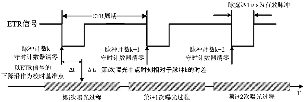
[0029] ETR timing is a completely independent hardware time synchronization logic circuit, timing strategy see figure 1 . Taking the falling edge of ETR as the reference point for timing, when ETR remains low for more than 1μs, it is considered that a valid ETR signal has been detected. At this time, if the ETR is disturbed by the external environment and generates jitter or glitches, and its low level cannot be maintained for 1 μs, it will be detected as an invalid signal. With effective ETR as the starting point of timing, start timing to generate ITR signal.

[0030] Take...


PUM


Abstract

The invention discloses a star sensor time synchronization signal timing method and a logic circuit. The method comprises the following steps: periodically producing an ITR signal by taking an ETR signal as the standard, thereby ensuring the consistence of the internal time standard and the external time standard; maintaining the high-precise and continuous output of the ITR signal when the ETR signal is lost; and immediately performing timing with the ETR signal when receiving the ETR signal again. The synchronous or asynchronous ITR signal is provided according to different demands of the star sensor.

Description

technical field [0001] The invention relates to the field of signal time calibration, in particular to a method and logic circuit for time synchronization signal calibration of a star sensor. Background technique [0002] The star sensor is currently the most accurate attitude sensor equipped with satellites, and it is an optical sensitive device that needs to image the starry sky. By driving the detector to image, extract and identify star points, and calculate its own attitude information. Taking the internal time reference (Internal Time Reference, ITR) signal as the exposure starting point, one frame is continuously exposed, and the center of mass of the star point and the corresponding exposure midpoint time are calculated. According to the time and attitude information, the angular velocity of the star sensor can be obtained, and then the optical axis pointing of the star sensor in the next frame period can be predicted to guide the image acquisition and information p...

Claims


Application Information

Patent Timeline
IPC IPC(8): H04J3/06
CPCH04J3/0638
Inventor 余路伟周琦毛晓楠任平川杨宵刘轩叶宋杭高原练达
Owner SHANGHAI AEROSPACE CONTROL TECH INST
Features
  • R&D
  • Intellectual Property
  • Life Sciences
  • Materials
  • Tech Scout
  • Unparalleled Data Quality
  • Higher Quality Content
  • 60% Fewer Hallucinations
Learn More