Monocular vision tracking method based on UUV underwater recovery

A monocular vision, underwater recovery technology, applied in image data processing, instruments, calculations, etc., can solve the problem of low tracking accuracy, and achieve the effect of ensuring accuracy and small amount of calculation

Active Publication Date: 2016-07-20
HARBIN ENG UNIV
View PDF5 Cites 14 Cited by
  • Summary
  • Abstract
  • Description
  • Claims
  • Application Information

AI Technical Summary

Problems solved by technology

[0005] The purpose of the present invention is to solve the problem of low tracking accuracy of the existing general visual tracking method in the case of UUV underwater recovery, and propose a monocular visual tracking method based on UUV underwater recovery

Method used


Image

  • Monocular vision tracking method based on UUV underwater recovery
  • Monocular vision tracking method based on UUV underwater recovery
  • Monocular vision tracking method based on UUV underwater recovery

Examples


specific Embodiment approach 1

[0031] Embodiment 1: A monocular vision tracking method based on UUV underwater recovery in this embodiment is specifically prepared according to the following steps:

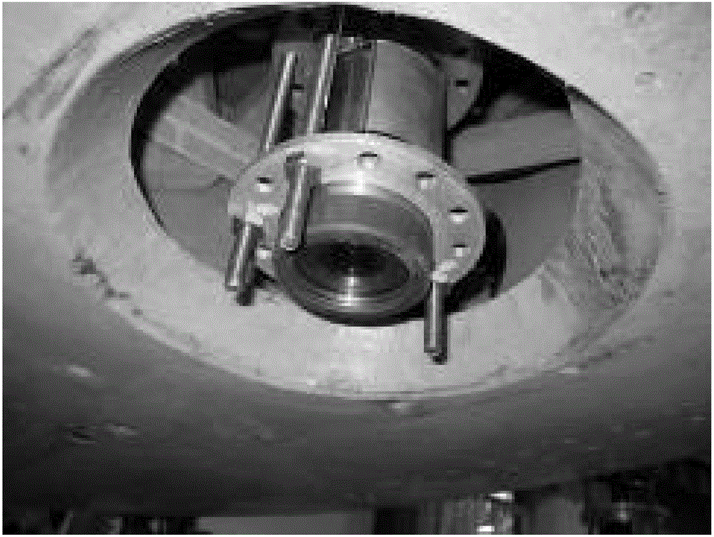
[0032] Step 1. When the target light source system appears in the field of view of the UUV (underwater unmanned vehicle) camera during the movement process, the UUV camera collects the sequence images of the target light source system;

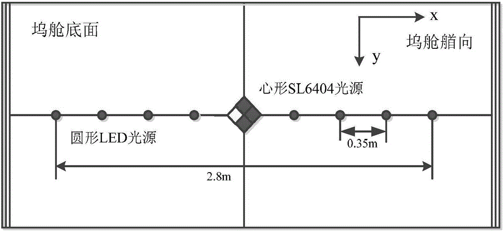
[0033] (Target light source system: Considering the actual situation of the UUV underwater load recovery method, the present invention adopts a linear light source array oriented to the line control position. Make the horizontal, vertical, and heading states reach the posture state. The characteristics of the target light source system are:

[0034] (1) The center points of 9 light sources are arranged on a straight line, and the distance between adjacent light sources is equal and fixed;

[0035] (2) The light source system is symmetrical to the center, the heart-shaped light...

specific Embodiment approach 2

[0046] Specific embodiment 2: The difference between this embodiment and specific embodiment 1 is: the minimum threshold ε=0.1 of selected iterative convergence in the step 2, the maximum number of iterations N=10, the sequence of the collected target light source system Select the heart-shaped light source target for the first frame of the image (manually use a rectangular frame to select the heart-shaped light source target for the first frame of image, and establish a target weighted model) to establish a target weighted model The specific process is:

[0047] Initialize the heart-shaped light source target with a rectangular box, and use this to mark the target's movement during tracking.

[0048] For the first frame image of the sequence image of the target light source system collected, a heart-shaped light source target is selected with a rectangular frame, and the center coordinates of the rectangular frame are assumed to be (O x ,O y ), where a and b are 1 / 2 of the...

specific Embodiment approach 3

[0071] Embodiment 3: The difference between this embodiment and Embodiment 1 or 2 is that in the step 3, the candidate target model is calculated in the current frame The specific process is:

[0072] The candidate target area refers to the area that may contain the target in each frame. Similar to (1), the candidate target model is expressed as:

[0073] p ^ u ( y ) = C h 1 Σ j = 1 n h k [ | | y - x i * h | | 2 ] δ [ b ...


PUM


Abstract

The present invention provides a monocular vision tracking method based on UUV underwater recovery. The present invention relates to a monocular vision tracking method based on UUV underwater recovery. The objective of the invention is to solve the problem that a general vision tracking method is low in tracking accuracy in the condition of UUV underwater recovery in the prior art. The method comprises the following steps: 1, collecting sequence images of a target light source system through a UUV camera; 2, building a target weight model; 3, calculating a candidate object model in the current frame; 4, obtaining a Bhattacharyya similarity coefficient; 5, calculating a weight coefficient; 6, obtaining the new position of a candidate object center according to the weight coefficient; 7, obtaining [Rho](y1); and 8, when ||y1-y0||<[Epsilon], stopping the tracking, or else, allowing y0=y1, returning back to the step 3, and if the current frame is the last one frame, finishing the tracking, or else, going on to read the next frame. The monocular vision tracking method based on UUV underwater recovery is applicable to the field of the monocular vision tracking of UUV underwater recovery.

Description

technical field [0001] The invention relates to a monocular vision tracking method based on UUV underwater recovery. Background technique [0002] When UUV performs tasks in the ocean, due to the limitation of battery capacity, its recovery is extremely important, and the underwater recovery of UUV has the advantages of small wind and wave turbulence, high concealment, and high strategic value; at the same time, the underwater recovery method is carried out by The docking platform carried by the ocean or the submarine is used to recover UUV. This method does not require the operation of lifting devices and personnel, and has broad development prospects. Cameras have been widely used in UUV. Compared with other sensors, they have the advantages of high short-range positioning accuracy, large amount of information obtained, strong adaptability, high resolution and low cost. [0003] In UUV underwater recovery, monocular vision has the advantages of easy installation and high ...

Claims


Application Information

Patent Timeline
Patent Type & Authority Applications(China)
IPC IPC(8): G06T7/20
CPCG06T2207/10016
Inventor 张伟孟德涛梁志成郭毅陈涛周佳加严浙平
Owner HARBIN ENG UNIV
Why Eureka
Try Eureka