Optical disk grabbing and placement mechanical arm used for optical disk juke-box

A technology of optical disc library and manipulator, which is applied to manipulators, chucks, manufacturing tools, etc., can solve the problems of poor movement stability, insufficient simple and fast movements, low efficiency of placing discs, etc., and achieves improved access efficiency, quick and easy movements, The effect of improving stability

Active Publication Date: 2019-02-05
BEIJING ZHONGKE KAIDI SOFTWARE CO LTD
View PDF9 Cites 3 Cited by
  • Summary
  • Abstract
  • Description
  • Claims
  • Application Information

AI Technical Summary

Problems solved by technology

[0004] In order to overcome the poor stability of the disc access manipulator in the existing disc library system when grabbing a single disc or multiple discs, the inability of the manipulator to accurately realize the stable detachment of discs one by one when the disc is placed by the manipulator, the low work efficiency of disc grabbing and placing discs, and the overall The process action is not simple and quick enough, etc. The present invention uses two stepping motors to cooperate with each other to grab and place the disc to realize the quick and easy action of the whole process, and uses the principle of a linear cam to control the retraction and expansion of the needle card to achieve stable hooking of the disc. The technical solutions such as the purpose of gradually pressing down the pressure plate bracket to make the discs fall off one by one accurately improve the disc access efficiency and stability of the disc storage device

Method used


Image

  • Optical disk grabbing and placement mechanical arm used for optical disk juke-box
  • Optical disk grabbing and placement mechanical arm used for optical disk juke-box
  • Optical disk grabbing and placement mechanical arm used for optical disk juke-box

Examples


Embodiment Construction

[0027] The present invention will be further described below in conjunction with the accompanying drawings and embodiments, and the described embodiments are only some embodiments of the present invention, not all embodiments. Based on the embodiments of the present invention, all other embodiments obtained by persons of ordinary skill in the art without creative efforts fall within the protection scope of the present invention.

[0028] The structures, proportions, sizes, quantities, etc. shown in the drawings attached to this specification are only used to match the content disclosed in the specification, for those who are familiar with this technology to understand and read, and are not used to limit the implementation of the present invention. Limiting conditions, so there is no technical substantive meaning, any modification of structure, change of proportional relationship or adjustment of size, without affecting the effect and purpose of the present invention, should sti...


PUM


Abstract

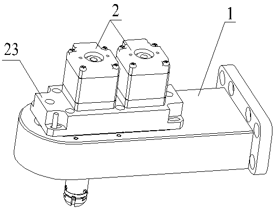
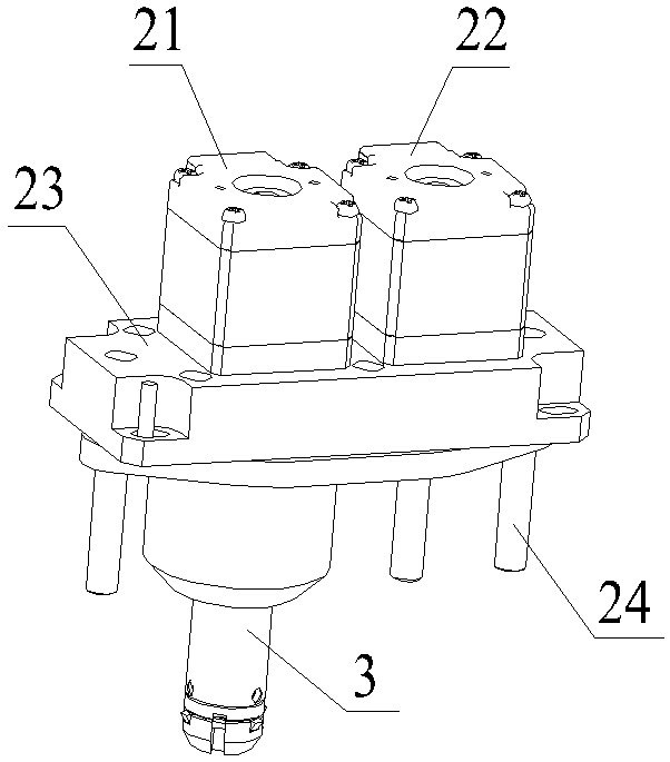
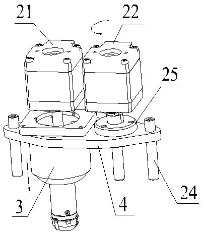
The invention discloses an optical disk grabbing and placement mechanical arm used for an optical disk juke-box. The optical disk grabbing and placement mechanical arm comprises a gripper support, a stepping motor assembly, a body, a pressure plate support, a sliding block assembly and a guide cap assembly. The gripper support can move along guide rail sliding blocks of the optical disk juke-box.The stepping motor assembly is mounted on the gripper support and comprises a disk taking stepping motor and a pressure plate stepping motor, and the body is connected with the disk taking stepping motor. When optical disks are grabbed, the disk taking stepping motor rotates so that the sliding blocks can move downwards, three needle clips are closed towards the center, the gripper support moves downwards so that the body can be inserted into center holes of the optical disks, the motor rotates reversely so that the sliding blocks can move upwards, the needle clips are expanded outwards to clamp the optical disks, and the gripper support moves upwards to take the optical disks. When the optical disks are placed, the needle clips are closed inwards, the pressure plate motor rotates so thatthe pressure plate support can move downwards step by step, the optical disks are pressed down one by one to be separated from the body, and the optical disks are placed.

Description

technical field [0001] The invention relates to the field of large-capacity optical storage devices, in particular to a disc grabbing and placing manipulator used in a disc library. Background technique [0002] Optical storage technology has the advantages of high data storage stability, long storage time, low energy consumption, and low maintenance costs. The optical storage technology is fully used in the optical storage. The optical disc library is a complex electromechanical integration system, including the optical disc storage part, the optical drive part, the manipulator and so on. Among them, the manipulator used for picking and placing the optical disc plays a key role in the entire system, which is related to the working efficiency and stability of the entire optical storage system. [0003] At present, there are a series of problems in the existing optical disc grabbing and placing manipulators on the market, such as poor movement stability when the manipulator ...

Claims


Application Information

Patent Timeline
Patent Type & Authority Applications(China)
IPC IPC(8): B25J15/00
CPCB25J15/0047
Inventor 张理宁萌白世杰张艺超
Owner BEIJING ZHONGKE KAIDI SOFTWARE CO LTD
Why Eureka
Try Eureka