Mask plate group for evaporation

A mask and evaporation technology, applied in vacuum evaporation coating, sputtering coating, ion implantation coating and other directions, can solve the problems affecting the realization of full screen, unable to meet the camera, unable to fix and so on

Active Publication Date: 2019-02-05
WUHAN CHINA STAR OPTOELECTRONICS SEMICON DISPLAY TECH CO LTD
View PDF7 Cites 12 Cited by
  • Summary
  • Abstract
  • Description
  • Claims
  • Application Information

AI Technical Summary

Problems solved by technology

[0005] The present invention provides a mask plate set for evaporation to solve the problem that the existing mask plate cannot be fixed on the mask plate body due to the shielding area separately provided in the corresponding area in the opening area, and it is difficult to realize the evaporation process of OLED. Unable to meet the needs of building the camera into the screen, and then affect the technical problems of the realization of the full screen

Method used


Image

  • Mask plate group for evaporation
  • Mask plate group for evaporation
  • Mask plate group for evaporation

Examples


Embodiment 1

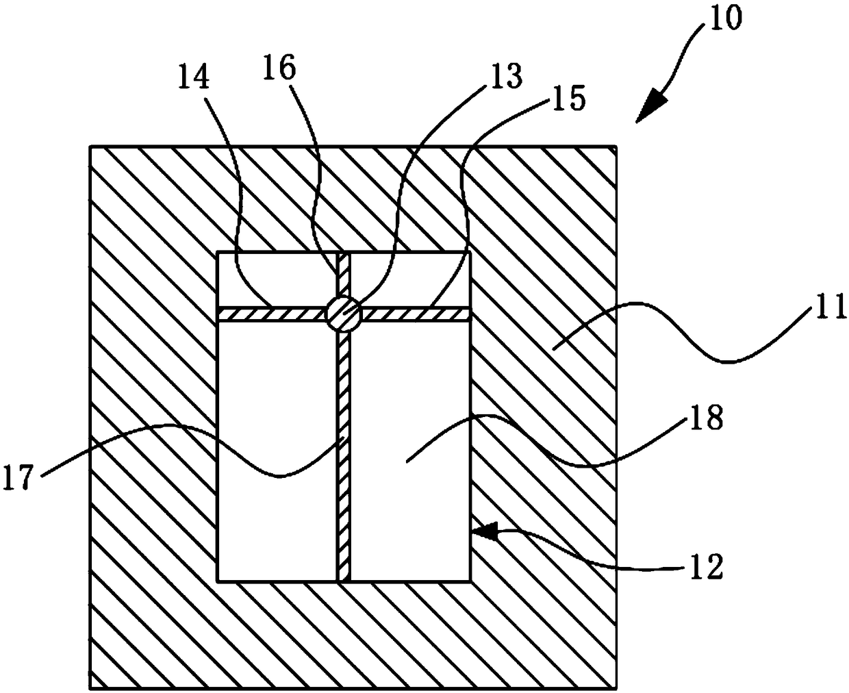
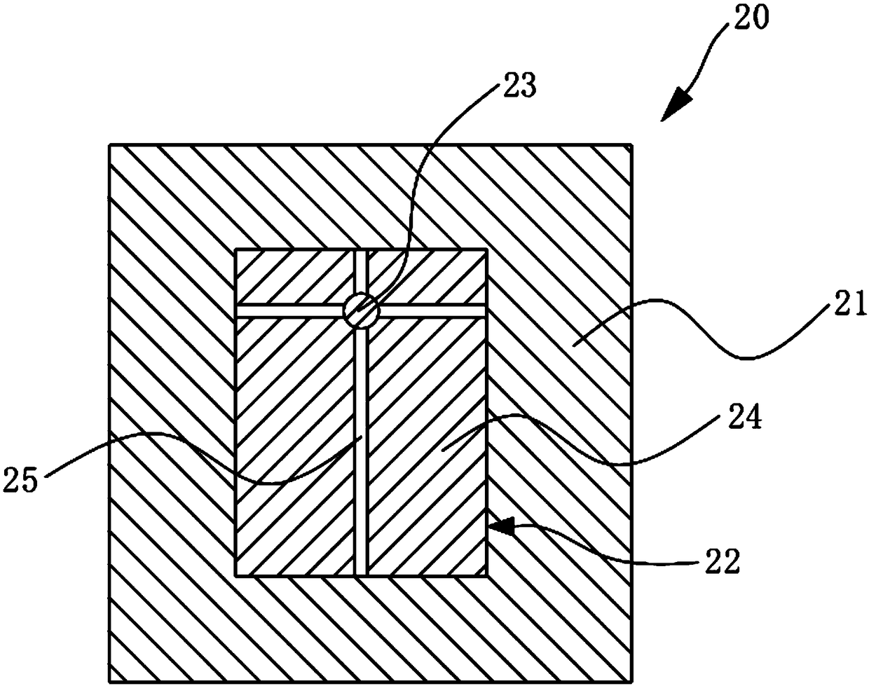
[0036] Such as figure 1 and figure 2 As shown, it is a schematic diagram of a matching mask used in the present invention. This embodiment provides a mask set, which includes two matching used masks, namely a first mask 10 and a second mask 20 .

[0037] Among them, such as figure 1 The first mask 10 shown includes a mask body 11 and an opening area 12, and the opening area 12 is provided with a shielding part 13, a first connecting piece 14, a second connecting piece 15, a third connecting piece 16, a second connecting piece Four connectors 17, and an evaporation area 18.

[0038] Wherein, one end of the first connecting piece 14, the second connecting piece 15, the third connecting piece 16, and the fourth connecting piece 17 are all connected to the shielding portion 13, and the opposite ends are connected to the shielding portion 13. The mask body 11 is connected. The shielding part 13 is fixed by four connecting pieces.

[0039] The first connecting part 14, the sec...

Embodiment 2

[0049] Such as figure 1 , 3 , 4, in order to carry out the evaporation process more stably, the evaporation can be divided into three times, the mask set provided in this embodiment includes three matching masks, namely the first mask 10, the second mask 30 and the third mask 40 .

[0050] The first mask provided in this embodiment has the same structure as the first mask provided in Embodiment 1 above, and details are not repeated here.

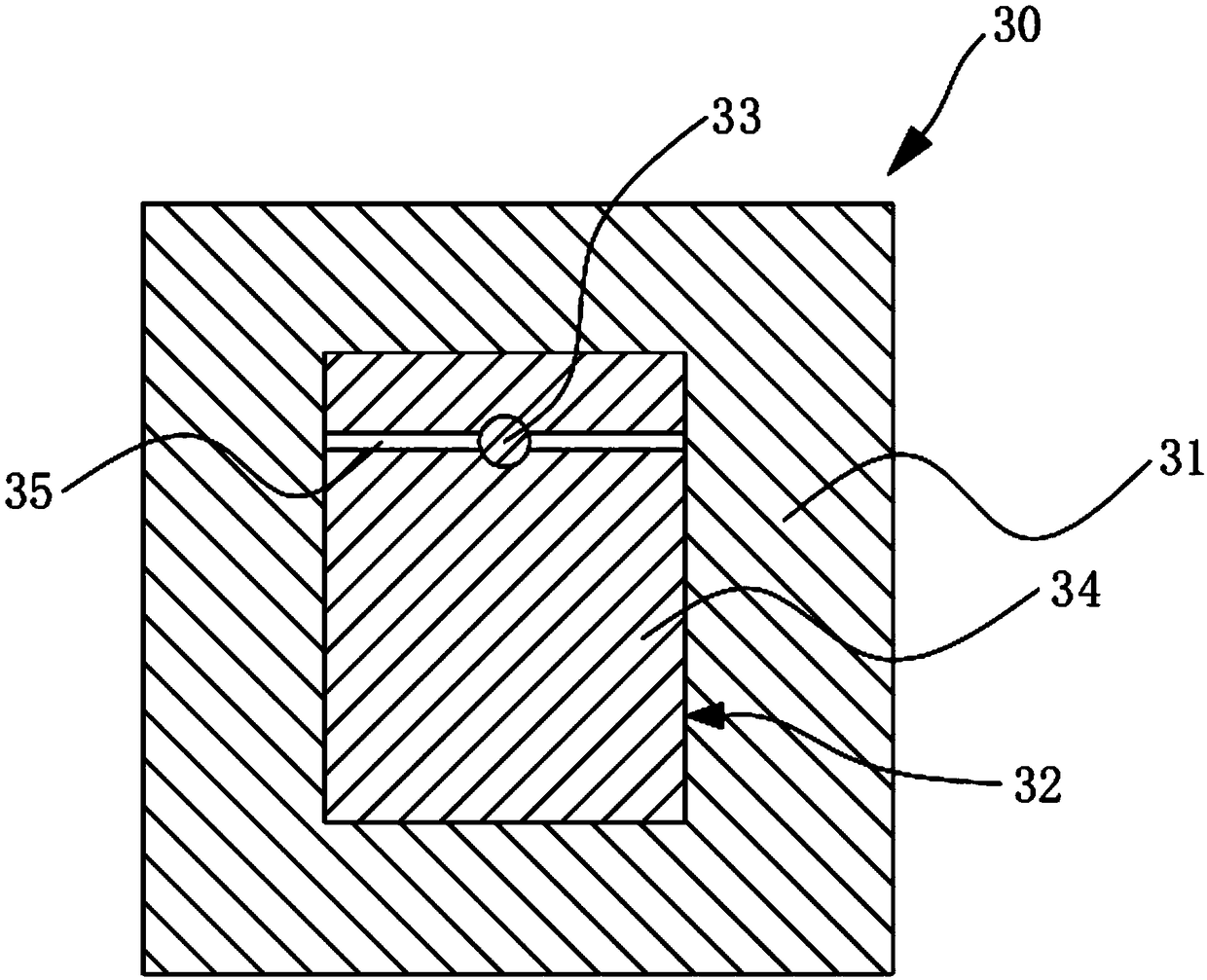
[0051] Such as image 3 As shown, the second mask 30 includes a mask body 31 and an opening area 32 , and the opening area 32 is provided with a shielding portion 33 , two connecting pieces 34 , and an evaporation area 35 .

[0052] Wherein, the two connecting pieces 34 are respectively located on two sides of the shielding portion 33 to connect and fix the shielding portion 33 with the mask body 31 .

[0053] The evaporation area 35 of the second mask plate 30 is divided into two second sub-evaporation areas by the shielding portion 33 ...

Embodiment 3

[0059] Such as figure 1 , Figure 5-8 As shown, the mask set provided in this embodiment includes five matching masks, namely the first mask 10, the second mask 50, the third mask 60, the fourth mask 70, and the fifth mask 80.

[0060] When performing evaporation, use the first mask plate 10 to perform the first evaporation, since the areas corresponding to the four connectors of the first mask plate 10 are blocked, the evaporation cannot be completed, in order to further fix For the shielding part, the subsequent coating can be divided into four evaporation processes. The second mask 50, the third mask 60, the fourth mask 70, and the fifth mask 80 provided in this embodiment are respectively for the first The regions of the first connector 14 , the second connector 15 , the third connector 16 , and the fourth connector 17 of the mask plate 10 that are not vapor-deposited are designed.

[0061] Such as Figure 5 As shown, the second mask 50 includes a mask body 51 and an o...


PUM


Abstract

The invention relates to a mask plate group for evaporation. The mask plate group for evaporation comprises at least two matched mask plates. Each mask plate comprises a mask plate body and an open area. A shielding part, at least one connecting part and an evaporation area are arranged in the open area; the connecting part is connected to the mask plate body and the shielding part; the connectingpart of one mask plate in the mask plate group is as same as the evaporation area of other mask plates in dimension and is overlaid with the evaporation area, and the evaporation areas of the at least two mask plates are matched. By providing a matched mask plate substep evaporation process, no evaporation materials are available in a special area of a screen, so that a camera is arranged in thescreen, and a comprehensive screen is facilitated.

Description

technical field [0001] The invention relates to the field of display technology, in particular to a mask template group for evaporation. Background technique [0002] At present, in the evaporation process part of the OLED device production process, the mask plate is mainly used as a mask mold to evaporate the material to the set position, and then complete the evaporation of red, blue, and green pixels. [0003] With the rapid development of electronic technology, the screens of display screens are becoming larger and larger. In order to provide users with a better visual experience, full screens have become a development trend of smart electronic terminals. In addition to the display screen, the front of the smart display screen also has components such as a front camera and earpiece, and the front camera and earpiece occupy a large area on the front of the smart terminal, thereby reducing the display area on the front of the display screen. [0004] At present, the scree...

Claims


Application Information

Patent Timeline
Patent Type & Authority Applications(China)
IPC IPC(8): C23C14/04C23C14/12C23C14/24
CPCC23C14/042C23C14/12C23C14/24C23C14/0021
Inventor 林治明
Owner WUHAN CHINA STAR OPTOELECTRONICS SEMICON DISPLAY TECH CO LTD
Why Eureka
Try Eureka