Synchronous wind tunnel testing device for aeroelasticity and wind pressure considering aerodynamic interference effect

A technology of wind tunnel test and interference effect, applied in aerodynamic test, measurement device, test of machine/structural components, etc., can solve problems such as inability to adjust the relative position of building structure

Active Publication Date: 2019-02-05
CHONGQING UNIV +1
View PDF6 Cites 13 Cited by
  • Summary
  • Abstract
  • Description
  • Claims
  • Application Information

AI Technical Summary

Problems solved by technology

If the simulation of multi-building structure layout cannot be realized in a set of test devices, it is impossible to truly simulate the influence of aerodynamic interference between the building structures in the actual building group on the aeroelastic and wind pressure characteristics of the building structure; although there are a few ex

Method used


Image

  • Synchronous wind tunnel testing device for aeroelasticity and wind pressure considering aerodynamic interference effect
  • Synchronous wind tunnel testing device for aeroelasticity and wind pressure considering aerodynamic interference effect
  • Synchronous wind tunnel testing device for aeroelasticity and wind pressure considering aerodynamic interference effect

Examples


Embodiment 1

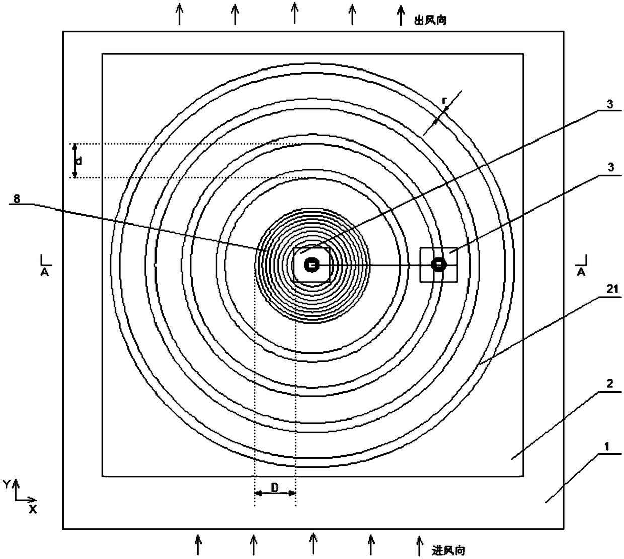
[0031] Such as Figure 1~5 , a synchronous aeroelastic-pressure measurement wind tunnel test device considering the effect of aerodynamic interference, including a test bench 2 fixed in the wind tunnel 1, and a test unit 3 arranged on the test bench 2, the test bench 2 is circumferentially Closed, with a number of concentric annular chute 21 on the top surface; the radial distance d between each chute 21 is equal to ensure that the auxiliary test unit can approach or move away from the main test unit in an equal adjustment manner relative to the main test unit unit, the opening width r of each chute 21 is equal to ensure the general installation of the auxiliary test unit; the test unit 3 is divided into two types, the main test unit and the auxiliary test unit, wherein the main test unit has one, which is arranged on all chutes 21 at the common center of the circle; there is at least one auxiliary test unit, which can be slidably arranged in the chute 21 and can be fixed by a...

Embodiment 2

[0047] Such as Figure 6 , 7 , The difference with Embodiment 1 is that in this embodiment, it also includes sealing blocks 9 arranged in the thickness direction of the top surface of the test bench 2; the sealing blocks 9 are arranged in pairs in each chute, and the opposite sides are Round head type, the away side is connected to the inner side of the test bench in the thickness direction through the return spring 10 arranged horizontally; under no external force, the sealing blocks 9 in each chute will push against each other in pairs to seal the chute 21; when there is a vertical When the external force acts, the sealing block 9 overcomes the active force of the back-moving spring 10 and is pushed away; From the first embodiment, it is not difficult to find that there is a risk of wind blowing even if the opening width r of the chute 21 is small, so the structure of the sealing block 9 is designed and used in conjunction with the return spring 10, so that the auxiliary te...


PUM


Abstract

The invention discloses a synchronous wind tunnel testing device for aeroelasticity and wind pressure considering the aerodynamic interference effect, and is applied to the field of wind tunnel testing devices. The device comprises a testing bench fixed in a wind tunnel, and a testing unit arranged on the testing bench. According to the synchronous wind tunnel testing device for aeroelasticity andwind pressure considering the aerodynamic interference effect, a wind pressure test and a aeroelasticity test can be synchronously carried out, and the influence of model vibration on wind load is comprehensively reflected; the air inertial force in the model vibration is measured, so that the obtained result of the aerodynamic force actually caused by wind is more accurate; the simulation of a multi-building structure layout is realized in one testing device, and the aerodynamic interference effect factor existing in a building group is taken into consideration; and meanwhile, it is convenient to adjust the relative position of each building structure, namely the distance between every two buildings, and the included angle relative to the wind direction, so that the research on the influence of the position layout of different buildings on aeroelasticity characteristics and wind pressure characteristics in one testing device is achieved, and the more practical theoretical research support is provided for the technical field of aeroelasticity characteristics and wind pressure characteristics.

Description

technical field [0001] The invention belongs to the field of wind tunnel test devices, and in particular relates to a synchronous aeroelastic-pressure measuring wind tunnel test device considering the aerodynamic interference effect. Background technique [0002] When designing super high-rise buildings, the wind-induced response of the structure is an important factor to be considered in the design process. Therefore, when designing super high-rise buildings, wind tunnel tests must be used to study the wind-induced effects of the test units. [0003] In the prior art, the functions of the test devices that can be used to study the wind-induced effect of the test unit are relatively single. For example, the test device used in the common wind tunnel pressure test cannot simulate the vibration of the model under the wind-induced effect. The pressure does not include the influence of structural vibration (the influence of fluid-solid coupling), so the measurement results canno...

Claims


Application Information

Patent Timeline
IPC IPC(8): G01M9/00
CPCG01M9/00
Inventor 陈增顺华建民宋军傅先枝黄海林
Owner CHONGQING UNIV
Why Eureka
Try Eureka