Linkage shaft for cable reel and cable unfolding and lifting device

A technology of interlocking shaft and cable reel, which is applied in the field of interlocking shaft for cable reel and cable spreading and lifting device, can solve the problems such as shaking and jumping of the cable reel of the supporting shaft, affecting the efficiency of cable unfolding, etc., so as to reduce shaking and Jitter, prevent excessive pulling, correct curvature effects

Active Publication Date: 2021-04-30
国网甘肃省电力公司金昌供电公司
View PDF15 Cites 0 Cited by
  • Summary
  • Abstract
  • Description
  • Claims
  • Application Information

AI Technical Summary

Problems solved by technology

[0003] 1. The cable reel is usually provided with a cable reel support hole for penetrating the support shaft. In order to facilitate the penetration of the support shaft, the outer diameter of the support shaft will be smaller than the cable reel support through hole. In this way, under the action of its own weight, the cable reel will It cannot be coaxial with the support shaft. When the cable is deployed, the cable reel will rotate off-axis relative to the support shaft under the action of external force. This will easily cause the support shaft or cable reel to shake or jump, which will inevitably It will affect the stability of cable deployment
[0004] 2. The support frame is not provided with a structure that can brake the rotation of the cable reel. In this way, under the action of external force, the cable reel is likely to release too many cables. returned or discarded), it is bound to affect the efficiency of cable deployment
[0005] 3. Since the cables are mostly stored and transported in the form of coils, the cables will be bent when unfolded, which will greatly affect the efficiency and quality of the subsequent processing of the cables by the operator

Method used


Image

  • Linkage shaft for cable reel and cable unfolding and lifting device
  • Linkage shaft for cable reel and cable unfolding and lifting device
  • Linkage shaft for cable reel and cable unfolding and lifting device

Examples


Embodiment 1

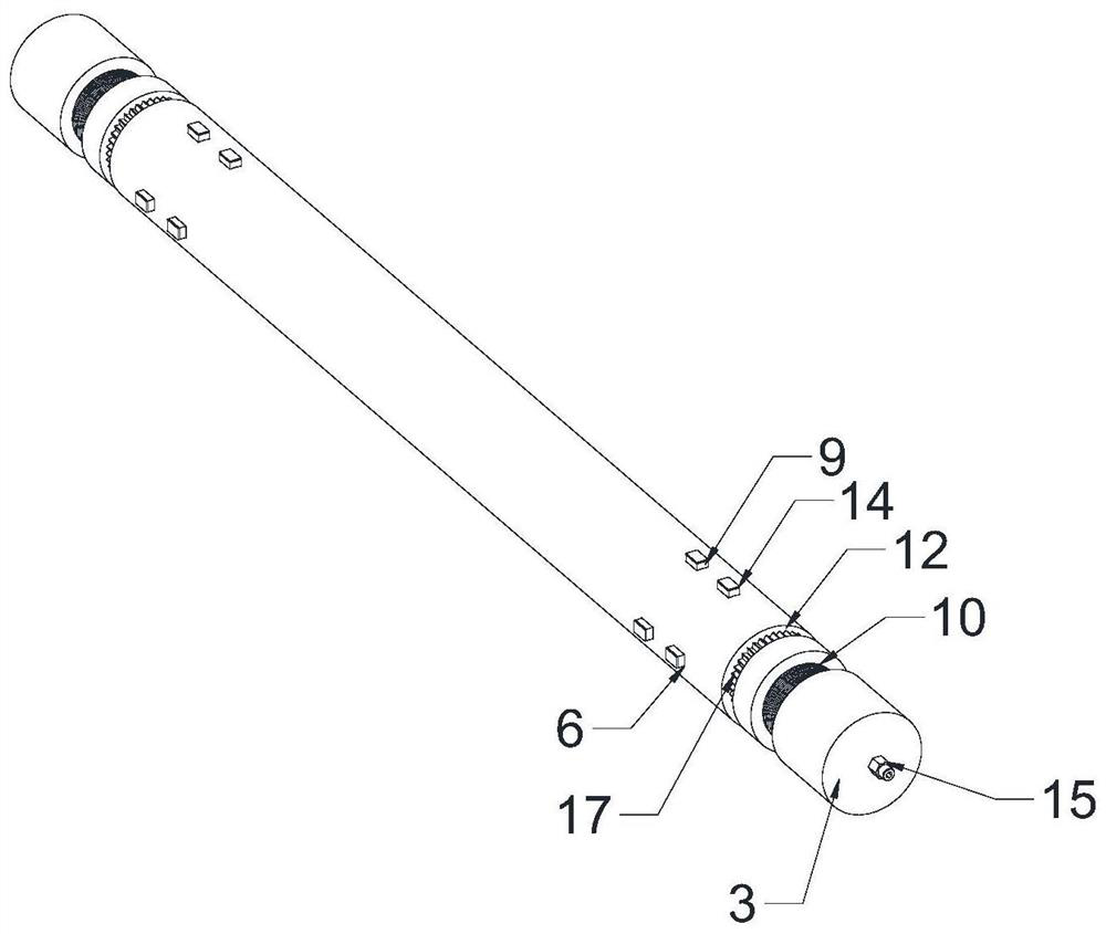
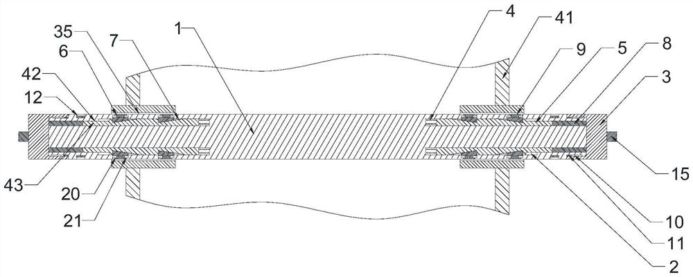
[0051] Such as Figure 1 to Figure 5 As shown, a connecting shaft for a cable reel includes a shaft body 1 and two end caps 3 that can be screwed with both ends of the shaft body 1 respectively, and both ends of the shaft body 1 are provided with a pressing assembly;

[0052] The abutment assembly includes an annular groove 2 opened at the end of the shaft body 1, the annular groove 2 runs through the outer end of the shaft body 1, and the groove bottom of the annular groove 2 along the axial direction of the shaft body 1 is connected by a sliding rod elastic member 4 There are several sliding rods 5 that can slide in the annular groove 2, and several sliding rods 5 are evenly distributed along the circumferential direction of the annular groove 2. The sliding rod 5 is provided with at least one sliding notch 7, and the sliding notch 7 The bottom of the groove is arranged on an inclined plane, and the groove depth of the sliding notch 7 is gradually deepened towards the area n...

Embodiment 2

[0067] In order to facilitate the braking of the shaft body 1, this embodiment makes the following further limitations on the basis of embodiment 1: both ends of the shaft body 1 are provided with brake assemblies;

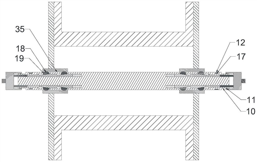
[0068] The brake assembly includes several brake teeth A17 arranged in a ring on the outer surface of the shaft body 1 .

[0069] In this embodiment, the arrangement of the braking teeth A17 can form an uneven structure on the outer surface of the shaft body 1 , so that it is easier to brake the shaft body 1 by inserting and fitting. In addition, regardless of the circumferential state of the shaft body 1 , the circular arrangement of the brake teeth A17 is designed to easily brake the shaft body 1 .

[0070] In order to avoid accidental wear of the brake tooth A17, preferably, an annular brake groove 12 is formed on the outer surface of the shaft body 1, and the brake tooth A17 is located in the brake groove 12.

[0071] In this way, the braking tooth A17 does n...

Embodiment 3

[0073] This embodiment makes the following further limitations on the basis of Embodiment 2: the outer surface of the end of the shaft body 1 is provided with a concave shaft body limiting groove 10, and the shaft body limiting groove 10 is provided with a shaft body thread part;

[0074] The inner surface of the end cap 3 is provided with an end cap limiting protrusion 11 which can cooperate with the shaft body limiting groove 10, and the position limiting protrusion 11 is provided with an end cap threaded section which is threadedly matched with the shaft body threaded section.

[0075] In this embodiment, the setting of the shaft limit groove 10 and the end cover limit protrusion 11 can limit the limit displacement of the end cover 3, so as to prevent the end cover 3 from moving excessively or even detaching from the shaft body 1, which will affect the operation of this embodiment. reliability and stable performance.


PUM


Abstract

The invention discloses a linkage shaft for a cable reel and a cable unfolding and lifting device. The linkage shaft comprises a shaft body and two end covers; abutting assemblies are arranged at the two ends of the shaft body; each abutting assembly comprises an annular groove formed in the end of the shaft body; the groove bottoms, in the axial direction of the shaft body, of the annular grooves are connected with a plurality of sliding rods capable of sliding in the annular grooves through sliding rod elastic pieces; each abutting assembly further comprises an abutting connection port set; and abutting rings which can be matched with the annular grooves in an embedded mode and can act on the sliding rods are arranged at the inner side ends of the end covers. According to the linkage shaft for the cable reel and the cable unfolding and lifting device, through the arrangement of sliding blocks capable of moving in the radial direction, penetrating fit of the shaft body and the cable reel can be easily achieved during assembly, abutting connection of the shaft body and the cable reel can be achieved during rotation or movement of the cable reel, and therefore shaking of the cable reel can be effectively reduced. Besides, only the shaft body needs to be braked, the cable reel can be effectively and accurately braked, and therefore the problem of excessive pulling can be prevented.

Description

technical field [0001] The invention belongs to the technical field of cable construction, and in particular relates to an interlocking shaft for a cable reel and a cable spreading and lifting device. Background technique [0002] Cable is a necessary material for the construction of power lines, and it is usually wound on a cable drum to enter the construction site in rolls. In order to facilitate the deployment of cables, the support shaft is usually used to penetrate the cable roll (the cable has been wound on the cable reel), the cable roll is set on the support shaft, and then the support shaft is placed on the support frame, and then driven by a jack or other The device raises the support shaft or support frame to suspend the cable coil, so that the cable can be deployed. But existing support device (support frame and support shaft) has following problem: [0003] 1. The cable reel is usually provided with a cable reel support hole for penetrating the support shaft. ...

Claims


Application Information

Patent Timeline
Patent Type & Authority Applications(China)
IPC IPC(8): B65H49/32B65H49/36B65H57/14B65H79/00
CPCB65H49/32B65H49/36B65H57/14B65H79/00B65H2701/34
Inventor 刘珏伶孙冬伟龚伟
Owner 国网甘肃省电力公司金昌供电公司
Why Eureka
Try Eureka