Handle unit with a movable locking cylinder

A handle and lock cylinder technology, applied in building locks, vehicle locks, lock applications, etc., can solve problems such as lock cylinder conflict, and achieve the effect of preventing swinging or sliding

Inactive Publication Date: 2019-02-05
HUF HULSBECK & FURST GMBH & CO KG
View PDF5 Cites 0 Cited by
  • Summary
  • Abstract
  • Description
  • Claims
  • Application Information

AI Technical Summary

Problems solved by technology

But in this type of lock cylinder, there is usually a conflict with the lock cylinder when installing the door handle located on the outside

Method used


Image

  • Handle unit with a movable locking cylinder
  • Handle unit with a movable locking cylinder
  • Handle unit with a movable locking cylinder

Examples


Embodiment Construction

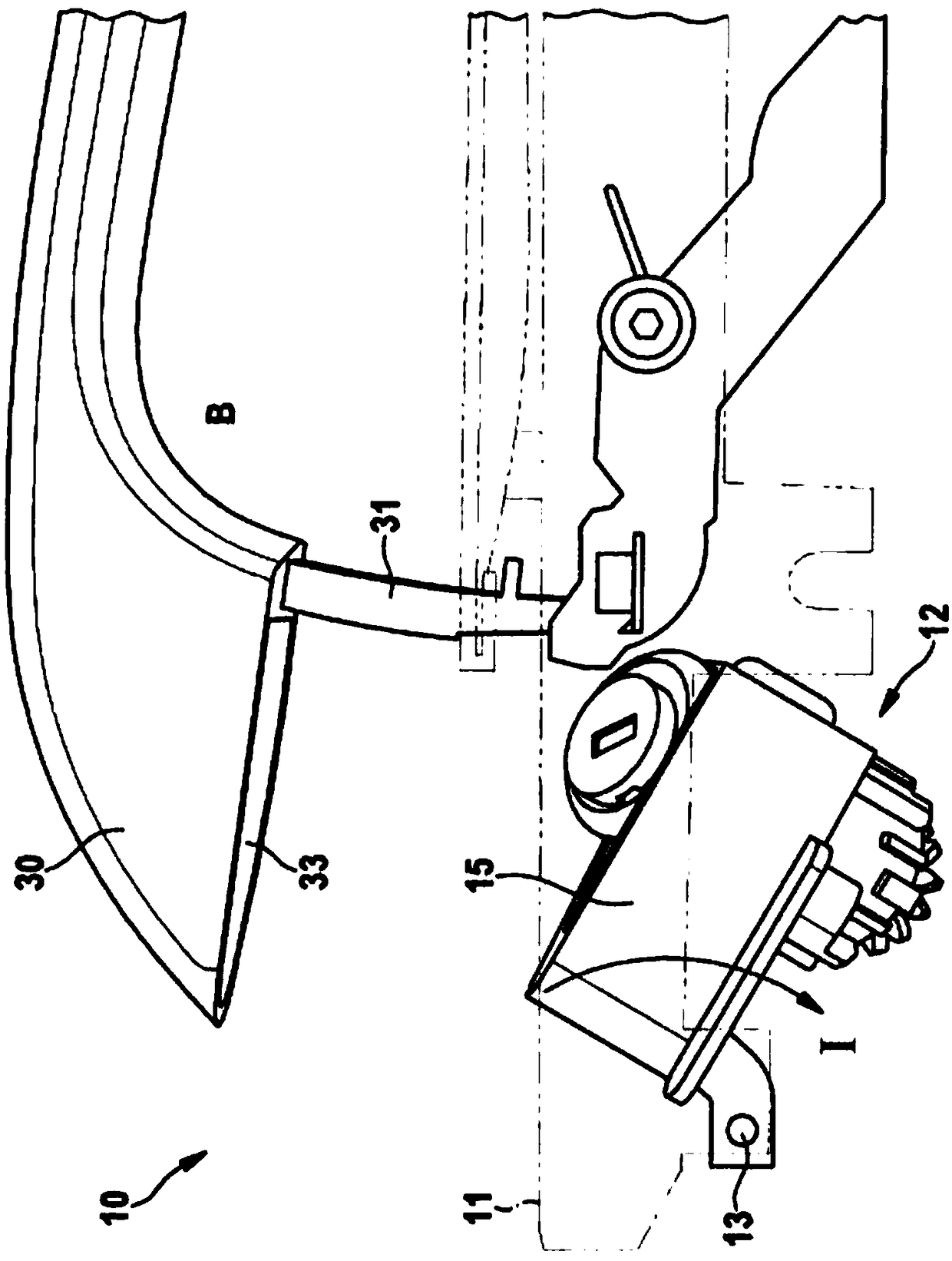
[0034] figure 1 A first embodiment of the handle unit 10 according to the invention is shown in . The handle unit 10 has a mounting bracket 11 with a lock cylinder 12 arranged thereon. The lock cylinder 12 has a housing 15 with a mounting support 13 arranged thereon, which is operatively connected to the mounting support 11 . Lock cylinder 12 in figure 1 In the installation position I, the door handle 30 is in the open position B. The door handle 30 also has a door handle pin 31 and a receptacle 33 for the lock cylinder 12 . Lock cylinder 12 in figure 1 In the middle, it is pivoted relative to the mounting bracket 11 at an angle in the direction of the vehicle interior around the mounting carrier 13 relative to the fastening position II. In this case, the door handle 30 can be mounted without conflict, without the door handle pin 31 colliding with the lock cylinder 12 , especially the housing 15 of the lock cylinder 12 .

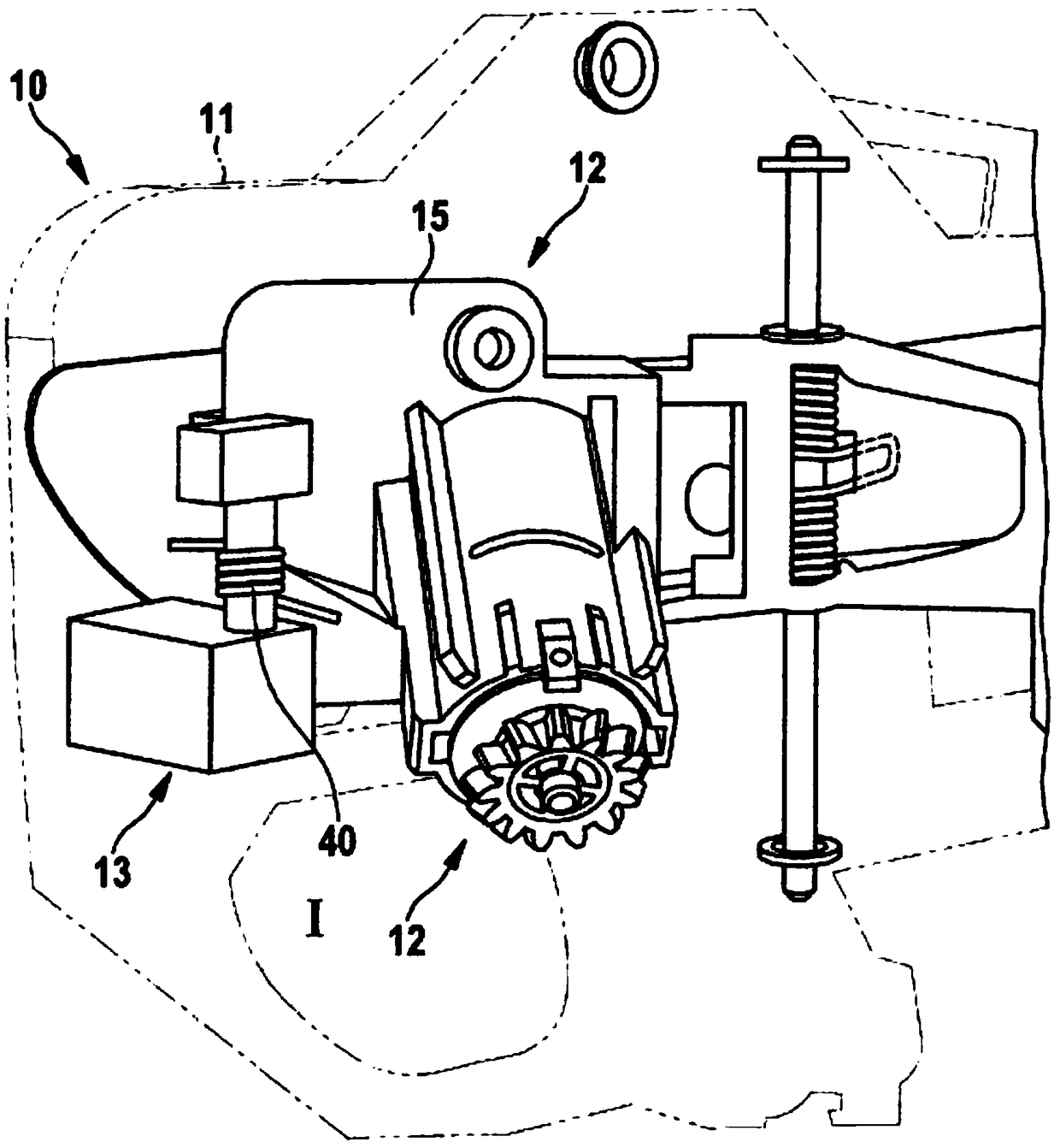
[0035] exist figure 2 A further embodiment of ...


PUM


Abstract

The invention relates to a handle unit (10) for a movable part (2) of a vehicle (1), comprising a mounting support (11) and a locking cylinder (12). The locking cylinder (12) is arranged on the mounting support (11) such that it can move, and can be moved into a securing position (II) and into at least one mounting position (I).

Description

technical field [0001] The invention relates to a handle unit for a movable part of a vehicle according to the preamble of the independent device claim and a method of mounting a door handle unit for a vehicle according to the independent method claim. Background technique [0002] It is known from the prior art to attach lock cylinders to vehicle doors from the outside, wherein such installed lock cylinders can be easily subjected to unauthorized manipulation. Furthermore, lock cylinders are known for use in door handles of vehicles, said lock cylinders being installable from the inside. However, with this type of lock cylinder, there are often conflicts with the lock cylinder when installing the door handle located on the outside. Contents of the invention [0003] The object of the present invention is to at least partially overcome the above-mentioned disadvantages known from the prior art. The object of the invention is in particular to achieve a simplified installa...

Claims


Application Information

Patent Timeline
Patent Type & Authority Applications(China)
IPC IPC(8): E05B79/06E05B85/16E05B85/06
CPCE05B79/06E05B85/06E05B85/16E05B85/10E05Y2900/531E05Y2900/546
Inventor 米尔科·罗林约尔格·穆勒
Owner HUF HULSBECK & FURST GMBH & CO KG
Why Eureka
Try Eureka