Eureka AIR delivers breakthrough ideas for toughest innovation challenges, trusted by R&D personnel around the world.

Optical anti-counterfeiting element and anti-counterfeiting product

A technology of optical anti-counterfeiting and components, which is applied in the field of optical anti-counterfeiting, and can solve problems such as coloring that cannot be colored, single effect, and limited matching relationship.

Active Publication Date: 2019-02-12
ZHONGCHAO SPECIAL SECURITY TECH +1
View PDF22 Cites 2 Cited by
  • Summary
  • Abstract
  • Description
  • Claims
  • Application Information

AI Technical Summary

Problems solved by technology

In order to achieve better coloring, this method has relatively large restrictions on the line width and concave depth of the micro-text, as well as the matching relationship between the two
Another method is to use micro-nano structures. For example, the patent document US20030179364 discloses the use of an optical absorption structure with a large aspect ratio to achieve black micro-text coloring. It is only a single micro-text coloring method and cannot achieve colorized coloring.
CN201180040580 multi-channel optical variable device discloses the use of gravure printing and other methods to achieve micro-image coloring, but based on the resolution limit of the printing process, only 30 micron lines can be printed, and the final effect is very single

Method used


Image

  • Optical anti-counterfeiting element and anti-counterfeiting product
  • Optical anti-counterfeiting element and anti-counterfeiting product
  • Optical anti-counterfeiting element and anti-counterfeiting product

Examples


Embodiment Construction

[0046] The optical anti-counterfeiting element according to the present invention and products using the optical anti-counterfeiting element will be described in detail below in conjunction with the accompanying drawings, so as to better understand the idea of ​​the present invention. It should be understood that the drawings and detailed description are only descriptions of preferred embodiments of the invention and are not intended to limit the scope of the invention in any way.

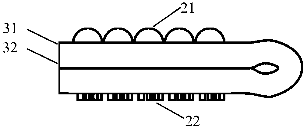
[0047] Such as figure 1As shown, the optical anti-counterfeiting element 1 according to an embodiment of the present invention includes: a substrate 2, which includes a first surface 31 and a second surface 32 opposite to each other, and a sampling layer formed on the first surface 31 21 and an image layer 22 formed on the second surface, the image layer 22 is associated with the sampling layer 21 and is respectively on different surfaces of the same area of ​​the substrate. The sampling layer con...


PUM

PropertyMeasurementUnit
Focal lengthaaaaaaaaaa

Abstract

The embodiment of the invention provides an optical anti-counterfeiting element and an optical anti-counterfeiting product using the optical anti-counterfeiting element, and belongs to the field of counterfeiting prevention. The optical anti-counterfeiting element comprises a base material, a sampling layer and an image layer. The base material comprises a first surface and a second surface whichare opposite to each other. The sampling layer is formed on at least part of the area of the first surface or the second surface. The image layer is formed on at least part of the area of the first surface or the second surface. The image layer comprises multiple micro image-text units and background areas between the micro image-text units. Each of the micro image-text units and / or the backgroundareas between the micro image-text units is at least partly composed of diffraction microstructures. The sampling layer and the image layer have certain relevance so that the sampling layer can conduct sampling and synthesizing on the image layer to form one or more macroscopic synthetic images. The optical anti-counterfeiting element has the characteristics that the optical anti-counterfeiting element is easy to recognize and it is difficult to counterfeit the optical anti-counterfeiting element.

Description

technical field [0001] The invention relates to the field of optical anti-counterfeiting, in particular to an optical anti-counterfeiting element and an optical anti-counterfeiting product using the optical anti-counterfeiting element. Background technique [0002] In order to prevent counterfeiting by means of scanning and copying, optical anti-counterfeiting technology is widely used in various high-security or high-value-added printed materials such as banknotes, cards and product packaging, and has achieved very good results. [0003] Patent documents such as CN101563640, CN101443692, CN101120139, CN101346244, US5712731, US0034082, US4765656, US4892336, CN1271106, CN1552589 and other patent documents disclose the same type of anti-counterfeiting elements with microlens arrays and micrographic arrays on the two surfaces of the substrate respectively. Wherein, the micro-text array is located near the focal plane of the micro-lens array, and a pattern with a certain depth o...

Claims


Application Information

Patent Timeline
IPC IPC(8): B42D25/328B42D25/20
CPCB42D25/20B42D25/328
Inventor 李欣毅朱军
Owner ZHONGCHAO SPECIAL SECURITY TECH
Why Eureka
Eureka Blog
Learn More