Fabric knitting method

A kind of braided fabric, the technology of the other side, applied in the weaving field of braided fabrics, can solve the problems of braided yarn disconnection, small neck hole, insufficient number of coils, etc., and achieve the effect of increasing the number of coils and suppressing yarn disconnection

Active Publication Date: 2019-02-12
SHIMA SEIKI MFG LTD
View PDF6 Cites 2 Cited by
  • Summary
  • Abstract
  • Description
  • Claims
  • Application Information

AI Technical Summary

Problems solved by technology

Here, in the case of knitting a U-shaped or V-shaped neck hole having an inclined edge portion having an angle with respect to the width direction of the knitted product (knitting width direction), there is a problem that the length of the neck hole is lower than the circumference of the neck hole. , the number of coils aligned along the neck hole is insufficient, and the neck hole shrinks to a smaller
If excessive tension is applied to the knitting yarn, the knitting yarn may break in the case of a knitting yarn that is easy to break

Method used


Image

  • Fabric knitting method
  • Fabric knitting method
  • Fabric knitting method

Examples


Embodiment approach 1

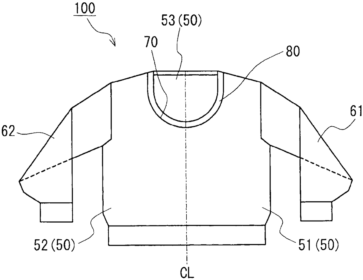
[0040] In Embodiment 1, an example in which a neckline is formed on a knitted pullover (knitted fabric) having a body and sleeves using the knitted fabric knitting method of the present invention will be described.

[0041] figure 1 The illustrated knitted pullover 100 (tubular knitted fabric) has a body 50 and sleeves (left sleeve 61 , right sleeve 62 ) of the set-in type. For convenience, the body 50 can be divided into a left front body 51 and a right front body 52 sandwiching the center line CL of the knitted pullover 100 , and a rear body 53 . A substantially U-shaped neckline 70 on the front body side is formed on the body 50 , and a cylindrical collar 80 is provided on the neckline 70 . In order to knit the sweater 100 using a flat knitting machine, the body 50 and the sleeves 61, 62 are knitted up to the position of the neckline 70, and then, with the front body 51, 52 and the back body 53 connected in a cylindrical shape, The number of stitches in the knitting width...

Embodiment approach

[0069] The method for knitting knitted fabrics of the present invention can also be used for knitting knitted fabrics other than sweaters. For example, the knitting method of the knitted fabric of the present invention can also be applied to knitting of openings such as knitted bags. Also, in addition to the one-side knitted fabric portion 1 , widening stitches may be formed on the other-side knitted fabric portion 2 to increase the number of stitches in the knitting width direction of the other-side knitted fabric portion 2 .


PUM


Abstract

The present invention provides a fabric knitting method. The fabric knitting method is a knitting method for a fabric in which the steps (A) to (C) are repeated a plurality of times. In the step (A),a first yarn supplying member is used, and an end portion side enhancing ring connected with an end portion coil on one side of a needle bed of one side of the fabric part is formed on the boundary ofone side of the fabric part and the end portion in the knitting width direction of the other side of the fabric part, and the end portion side enhancing ring is arranged on the outer side in the knitting width direction of the other side of the fabric part. In the step (B), a part of the one knitted fabric portion is moved toward the boundary side, and at least one stitch insertion space is formed in the knitting width of the one knitted fabric portion. In the step (C), the second yarn supplying member is used to form an inner side widening ring that is connected to the existing coil close tothe insertion space in the one side knitted fabric portion, and the coil insertion space is filled with the existing coil or the inner side reinforcing ring. .

Description

technical field [0001] The present invention relates to a method of knitting a knitted fabric in which the number of stitches in the knitting width direction of the one-side knitted fabric portion is increased for the one-side knitted fabric portion and the other-side knitted fabric portion connected in a cylindrical shape. Background technique [0002] Patent Document 1 discloses a technique of knitting a knitted fabric (knitted fabric) having a collar using a flat knitting machine. Here, in the case of knitting a U-shaped or V-shaped neck hole having an inclined edge portion having an angle with respect to the width direction of the knitted product (knitting width direction), there is a problem that the length of the neck hole is lower than the circumference of the neck hole. , the number of coils arranged along the neck hole is insufficient, and the neck hole shrinks to a smaller size. In Patent Document 1, as a technique for solving such a problem, empty needles are for...

Claims


Application Information

Patent Timeline
Patent Type & Authority Applications(China)
IPC IPC(8): D04B1/24
CPCD04B1/246D04B1/108D04B7/32
Inventor 登尾佳史山内贤岛崎宜纪由井学
Owner SHIMA SEIKI MFG LTD
Why Eureka
Try Eureka