Control method used for unfreezing device

A control method and chamber technology, applied in the field of thawing, can solve problems such as long thawing time, uneven heating of ingredients, and damage to the quality of ingredients, and achieve the effect of improving thawing efficiency

Pending Publication Date: 2019-02-12
QINGDAO HAIER SMART TECH R & D CO LTD
View PDF0 Cites 2 Cited by
  • Summary
  • Abstract
  • Description
  • Claims
  • Application Information

AI Technical Summary

Problems solved by technology

[0003] However, in the prior art, the air thawing operation is simple, but the thawing time is too long, the surface of the food is easily oxidized, and the juice loss is serious after thawing; the water thawing is not only time-consuming, but also bacteria and microorganisms are easy to grow on the surface of the food during the thawing process, seriously Affect food quality; heating wire or heating tube for thawing, the heating efficiency is low and the temperature of the food after thawing is uneven; when the microwave oven based on the magnetron technology thaws the food, the electromagnetic wave emitted by the magnetron as the emission source cannot be controlled The phase and poor directionality of the food will lead to uneven heating inside and outside the food, which will cause the temperature difference between the inside and outside of the thawed food to be too large, the juice will be lost too much, and the quality of the food will be seriously damaged.

Method used


Image

  • Control method used for unfreezing device
  • Control method used for unfreezing device
  • Control method used for unfreezing device

Examples


Embodiment Construction

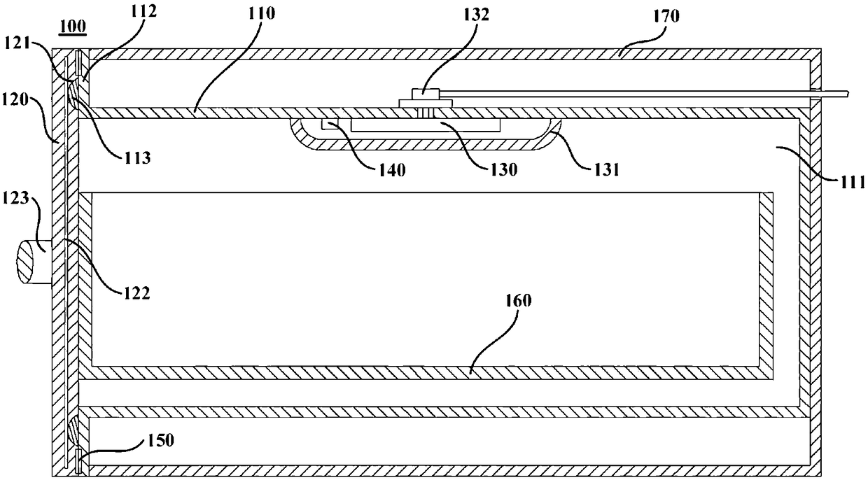
[0046] figure 1 is a schematic cross-sectional view of a thawing device 100 according to an embodiment of the present invention. see figure 1 , the thawing device 100 may include a cylinder body 110 , a device door 120 , a radio frequency generating module 190 and a radio frequency antenna 130 . Specifically, the barrel 110 defines a thawing chamber 111 for placing the object to be processed. The device door 120 can be arranged at the access opening of the thawing chamber 111 for opening and closing the access opening of the thawing chamber 111 . The radio frequency generating module 190 can be configured to generate radio frequency signals (generally refer to radio frequency signals with a frequency of 300KHz-300GHz). The radio frequency antenna 130 can be a rectangular metal sheet. The radio frequency antenna 130 may be composed of a transmitting antenna and a receiving antenna arranged side by side along the lateral direction or front-to-back direction of the thawing de...


PUM


Abstract

The invention provides a control method used for an unfreezing device. The unfreezing device comprises a barrel, a device door body, a radio frequency generation module and a radio frequency antenna.An unfreezing cavity used for containing a to-be-processed object is defined in the barrel. The device door body is arranged at the position of a picking and placing opening of the unfreezing cavity and used for opening and closing the picking and placing opening of the unfreezing cavity. The radio frequency antenna is arranged at the position of the inner wall of the unfreezing cavity and electrically connected with the radio frequency generation module. The control method includes the steps that the optimal unfreezing frequency for unfreezing the to-be-processed object placed in the unfreezing cavity is confirmed; the radio frequency generation module generates a radio frequency signal with the frequency being the optimal unfreezing frequency; and the radio frequency antenna generates radio frequency waves with the corresponding frequency in the unfreezing cavity according to the radio frequency signal, and the to-be-processed object is unfrozen. According to the control method, by confirming the optimal unfreezing frequency for unfreezing the to-be-processed object and making the radio frequency generation module generate the radio frequency signal with the frequency being the optimal unfreezing frequency to unfreeze the to-be-processed object, the unfreezing frequency is improved, the unfreezing time is shortened, and then the unfreezing convenience is improved for users.

Description

technical field [0001] The invention relates to the field of thawing, in particular to a control method for a thawing device. Background technique [0002] The freezer compartment of a general household refrigerator (the temperature of the freezer compartment is generally -18°C) is used to store food that will not be eaten in a short period of time, especially various meats. Before cooking the food stored in the freezer, the user usually Frozen ingredients need to be thawed to about -5°C. Meat at this temperature is easy to cut and will not be cut because the temperature is too low. If the temperature is too high, it is difficult to cut and the cut meat or sliced ​​meat will not be shaped. [0003] However, in the prior art, the air thawing operation is simple, but the thawing time is too long, the surface of the food is easily oxidized, and the juice loss is serious after thawing; the water thawing is not only time-consuming, but also bacteria and microorganisms are easy to...

Claims


Application Information

Patent Timeline
Patent Type & Authority Applications(China)
IPC IPC(8): F25D23/12F25D29/00A23L3/365
CPCA23L3/365F25D23/12F25D29/00H05B6/48H05B6/62
Inventor 张冰陶瑞涛王霁昀闫茂松田红荀
Owner QINGDAO HAIER SMART TECH R & D CO LTD
Why Eureka
Try Eureka