Wall mounting type frozen chicken unfreezing mechanism and unfreezing method

A wall-mounted, chicken technology, which is applied in the direction of freezing/cooling to preserve meat/fish, etc. It can solve the problems of long thawing time, inability to hang the mechanism, poor heating uniformity of chicken, etc.

Inactive Publication Date: 2015-04-29
CHINA JILIANG UNIV
View PDF8 Cites 4 Cited by
  • Summary
  • Abstract
  • Description
  • Claims
  • Application Information

AI Technical Summary

Problems solved by technology

[0003] The invention provides a wall-mounted frozen chicken thawing mechanism and a thawing method with uniform heating of chicken, high heat utilization rate of thawing water, and small quality deterioration of chicken, which solves the problem of uniform heating of chicken when the existing thawing device thaws frozen chicken Poor performance, low heat utilization rate of thawed water, long thawing time, large amount of quality deterioration, and the mechanism cannot be suspended

Method used


Image

  • Wall mounting type frozen chicken unfreezing mechanism and unfreezing method
  • Wall mounting type frozen chicken unfreezing mechanism and unfreezing method
  • Wall mounting type frozen chicken unfreezing mechanism and unfreezing method

Examples


Embodiment 1

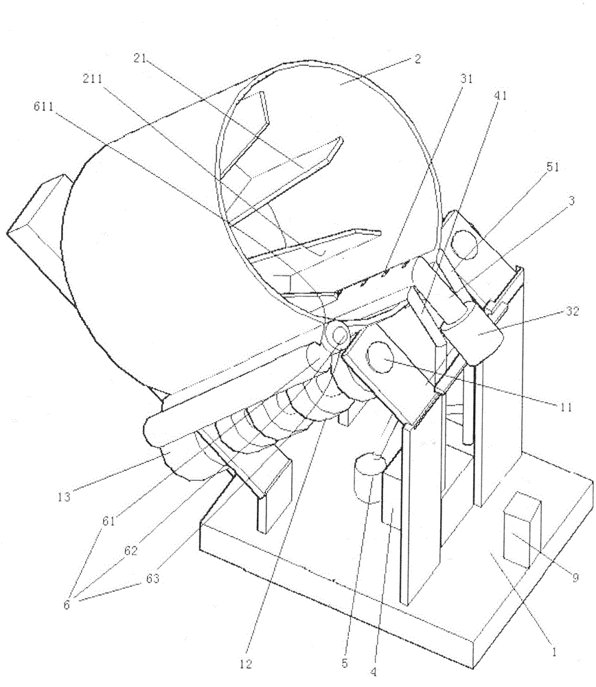
[0030] Embodiment one, see figure 1 A wall-mounted frozen chicken thawing mechanism includes a frame 1, a bucket 2, an air blowing pipe 3, a thermostat 4, a circulation pump 5 and a wiping mechanism 6.

[0031] The frame 1 is provided with a pair of support shafts 11 in an inclined state. The support shaft 11 is rotatably connected to the frame 1 . A pair of support shafts 11 are distributed along the left and right directions. The two supporting shafts 11 are parallel. The support shaft 11 is provided with several drive wheels 12 distributed along the axial direction. The one on the left side in the pair of supporting shafts 11 is connected with the driving motor 13 . The drive motor 13 is connected to the lower end of the support shaft. This can improve the stability of the present invention. The frame 1 is also provided with a suspension frame 9 .

[0032] Bucket 2 is the little truncated cone shape of bottom big upper end (being open end). The bucket 2 rests on the...

Embodiment 2

[0072] Embodiment two, the difference with embodiment one is:

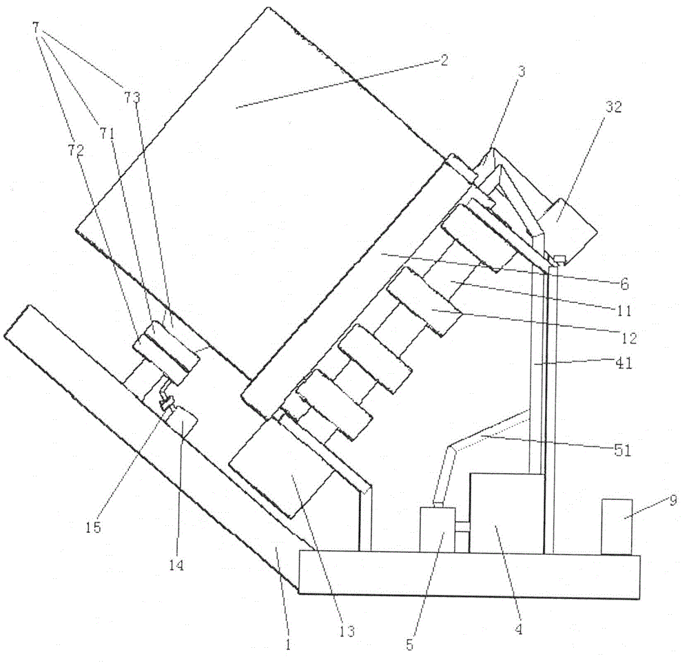
[0073] see Figure 5 , also includes a coating heating mechanism 8. Suspension bar 9 is the arc structure that arches downwards (certainly upwards is also possible). The coating heating mechanism 8 includes a case shell 80 , a swing rod 87 and a driving motor 88 . The swing rod 87 is provided with an applicator head 871 . The applicator head 871 is ring-shaped. The coating head 871 is sheathed on the suspension rod 91 . The drive motor 88 is fixed to the case 80 . The case shell 80 is fixed together with the frame 1.

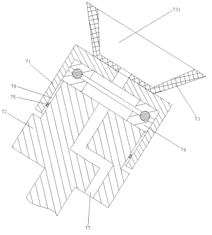
[0074] see Figure 6 , The coating heating mechanism 8 also includes a power input shaft 86, a swing shaft 81, a swing gear 82, a forward drive gear 83, a reverse drive gear 84 and a reversing gear 85 located in the case. The swing shaft 81 is rotatably connected to the casing 80 . The swing gear 82 is connected to the swing shaft 81 . The forward drive gear 83 is connected to a power inpu...

Embodiment 3

[0078] Embodiment three, the difference with embodiment two is:

[0079] see Figure 8 , the squeeze roller 61 is also rotatably connected to the frame 1 (see figure 1 )of. Squeeze roll also is by drive motor 13 (referring to figure 1 )Driven. The wiping mechanism 6 also includes a water receiving tank 66, that is, the water receiving tank replaces the gutter. The water receiving groove 66 is located below the extrusion place of the extrusion roller 61 . The linear velocity of the contact point 632 between the water-absorbing block and the surface of the squeeze roller is equal to the linear velocity of the surface of the squeeze roller 611. During use, the rotation direction of the mandrel 62 is from bottom to top, that is, direction C in the figure, which is opposite to the rotation direction of the first embodiment. The rotation direction of squeeze roller 61 is opposite to the rotation direction of the mandrel.


PUM


Abstract

The invention relates to the field of chicken processing. A wall mounting type frozen chicken unfreezing mechanism comprises an air blowing pipe, a thermostat, a circulating pump, a rack and a bucket, wherein the rack is provided with a supporting seat and a supporting shaft in an inclined state, the bucket is laid on the supporting shaft in a peripheral contact way, the supporting base is arranged on the bottom wall of the bucket, the inner peripheral surface of the bucket is connected with a plurality of pushing blocks which are distributed along the peripheral direction of the bucket, the air blowing pipe is inserted into the bucket via an opening of the bucket, the air blowing pipe is connected with the rack, the circulating pump is used for enabling water to circulate between the bucket and the thermostat, and the rack is provided with a suspension rod. The wall mounting type frozen chicken unfreezing mechanism and unfreezing method which are provided by the invention have the advantages that chicken is uniformly heated, heat utilization rate of melt water is high and degradation of the chicken is low in quality, and the problems that chicken heating uniformity is poor, heat utilization rate of the melt water is low, unfreezing time is long, quality degradation degree is high and a mechanism can not be suspended when the existing unfreezing device is used for unfreezing frozen chicken are solved.

Description

technical field [0001] The invention relates to the field of chicken processing, in particular to a wall-mounted frozen chicken unsorting mechanism and a thawing method. Background technique [0002] Existing methods for thawing frozen chicken include natural air thawing and hydrostatic thawing. The natural air thawing method is to take the frozen chicken out of the refrigerator, put it in a plastic frame, and thaw it in a natural environment at room temperature (10±2)°C. The static water thawing method is to take the frozen chicken out of the refrigerator, completely immerse it in the water in the thawing box (hereinafter, the water used for thawing is called thawing water), and thaw it in a way that keeps the temperature of the thawing water in the thawing box constant. . In the Chinese Patent No. 2005200804466, the publication date is August 23, 2006, and the patent document named "constant temperature cycle thawing box" discloses a thawing mechanism for hydrostatic tha...

Claims


Application Information

Patent Timeline
Patent Type & Authority Applications(China)
IPC IPC(8): A23B4/07
Inventor 李梅陈卫民蔡慧
Owner CHINA JILIANG UNIV
Why Eureka
Try Eureka