
Insecticidal lamp high-voltage grid structure with layering screen with hooks for scraping off insects

A high-voltage power grid and insecticidal lamp technology, which can be used in the fields of trapping or killing insects, applications, animal husbandry, etc., and can solve the problems of reducing spectral attraction, increasing resistance value, blocking the electric shock of insecticidal lamps, etc.

Inactive Publication Date: 2019-02-15
林叶青
View PDF0 Cites 2 Cited by
  • Summary
  • Abstract
  • Description
  • Claims
  • Application Information

AI Technical Summary

Problems solved by technology

[0004] In view of the deficiencies in the prior art, the purpose of the present invention is to provide a high-voltage power grid structure for insecticidal lamps with hooks to scrape insects, so as to solve the problem of electric shock when mosquitoes fly into the insecticidal lamps and come into contact with the high-voltage power grid. Excessive burning and sticking to the power grid will accumulate mosquito corpses for a long time, which will cause the light of the insecticidal lamp to be covered by the volume of mosquitoes, reduce the spectral attraction, and also block the electric shock of the insecticidal lamp, resulting in the accumulation of mosquito corpses and increasing the resistance value. The amount of electric shock current is reduced, and the high-voltage electric discharge is not enough to kill insects and can only be stunned

Method used


Image

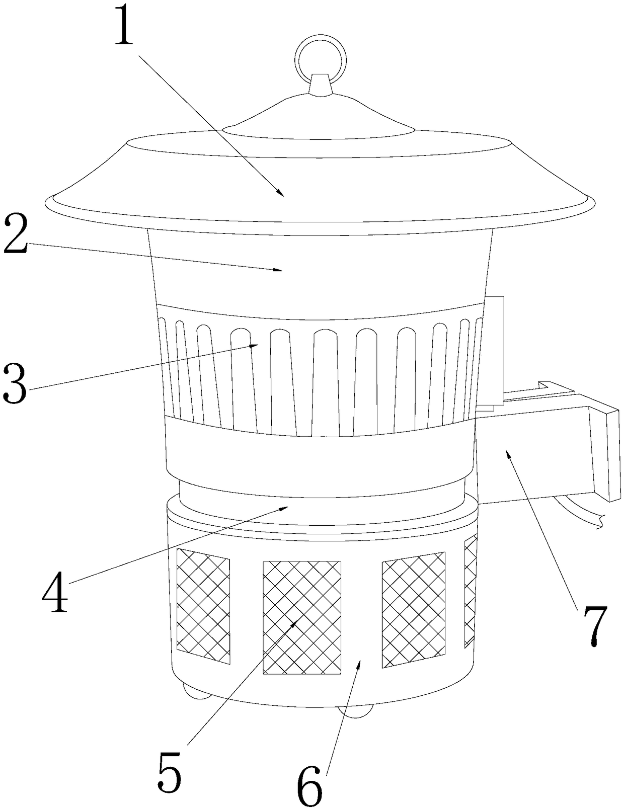
  • Insecticidal lamp high-voltage grid structure with layering screen with hooks for scraping off insects
  • Insecticidal lamp high-voltage grid structure with layering screen with hooks for scraping off insects
  • Insecticidal lamp high-voltage grid structure with layering screen with hooks for scraping off insects

Examples


Embodiment Construction

[0025] In order to make the technical means, creative features, goals and effects achieved by the present invention easy to understand, the present invention will be further described below in conjunction with specific embodiments.

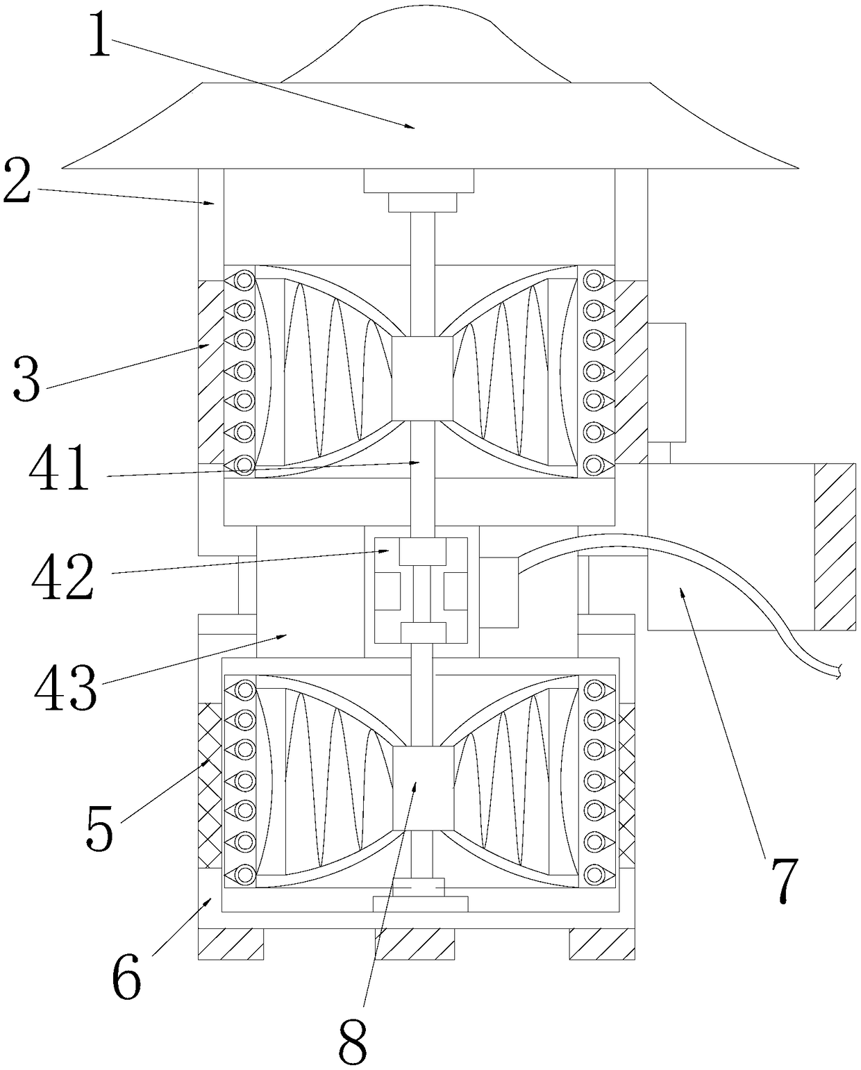
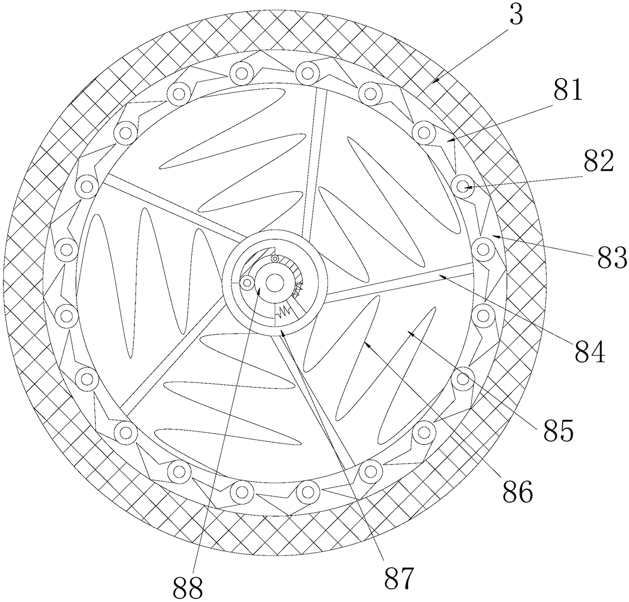
[0026] see Figure 1-Figure 5 , the present invention provides an insecticidal lamp high-voltage power grid structure with a layered screen for scraping insects with hooks. Groove 4, screen plate 5, base lamp tube 6, clip support 7, power grid amplifier 8, two power grid amplifiers 8 are provided and nested in the insecticidal lamp tank body 2 and the base lamp tube 6 respectively , the insecticidal lamp tank 2 and the fence groove ring 3 are buckled together and the axes are collinear, and the insecticidal lamp tank 2 and the base lamp tube 6 are respectively nested on the upper and lower sides of the biaxial motor slot 4 , the clip support 7 is welded on the right side of the biaxial motor slot 4, the power distribution block of the biaxial mot...


PUM


Abstract

The invention discloses an insecticidal lamp high-voltage grid structure with a layering screen with hooks for scraping off insects. The insecticidal lamp high-voltage grid structure comprises a top cover disc, an insecticidal lamp tank, a fence groove ring, a double-shaft motor groove, a screen plate, a base lamp barrel, a clip-clasping support and grid amplifiers. The two grid amplifiers are nested in the insecticidal lamp tank and the base lamp barrel respectively, the insecticidal lamp tank and the fence groove ring are buckled together, the axes are collinear, and the insecticidal lamp tank and the base lamp barrel are nested on the upper side and the lower side of the double-shaft motor groove respectively. According to the insecticidal lamp high-voltage grid structure, the double-shaft motor groove and the grid amplifiers cooperate, a motor body is started, a shaft lever drives a speed regulating carbon brush holder to be in linkage with a shaft sleeve to rotate, and therefore aPC conductive plate is dragged to be powered on with a Tesla wire pipe to rotate, then a Tesla amplified electromagnetic field is formed, a high-voltage grid structure formed by the fence groove ringand the mesh plate achieves an amplification effect, the insect killing covering current intensity is amplified, and it is avoided that the insect killing effect is weakened due to impurity interference.

Description

technical field [0001] The invention relates to a high-voltage power grid structure for an insecticidal lamp with a layered screen for scraping insect bodies with hooks, and belongs to the field of high-voltage power grids. Background technique [0002] The insecticidal lamp is a simple device for indoor and outdoor repelling mosquitoes. Most of the indoor insecticidal lamps are developed for the mosquito repellent effect. They need to use the spectral brightness to attract mosquitoes to catch mosquitoes. The high-voltage power grid of the insecticidal lamp is the part that shocks mosquitoes after capture. However, the accumulation or contamination of mosquitoes on the power grid will reduce the working efficiency of the power grid. The shortcomings of the current technology to be optimized are: [0003] When mosquitoes fly into the insecticidal lamp and come into contact with the high-voltage power grid, they will be electrocuted and burnt and stick to the power grid. Mosqu...

Claims


Application Information

Patent Timeline
IPC IPC(8): A01M1/22A01M1/04
CPCA01M1/223A01M1/04
Inventor 林叶青
Owner 林叶青
Learn More