Inertial centrifugal shoe rack device for shoe washing machine

The technology of a shoe washing machine and a shoe rack, which is applied in the field of shoe washing machine devices, can solve the problems of unguaranteed scrubbing effect, increased use cost, and increased production cost, and achieves the advantages of convenient and fast disassembly and assembly of shoes, simple structure, and resource saving Effect

Pending Publication Date: 2019-02-15
WENZHOU UNIVERSITY
View PDF7 Cites 5 Cited by
  • Summary
  • Abstract
  • Description
  • Claims
  • Application Information

AI Technical Summary

Problems solved by technology

[0002] Shoes are easy to get dirty and difficult to clean
Scrubbing with bare hands is time-consuming and laborious. It is too expensive to entrust a special shoe washing shop to wash shoes, the scrubbing effect cannot be guaranteed, and it is easy to damage the shoes. Therefore, the problem of shoe cleaning has always been troubled by people.
Therefore, special-purpose shoe washing machines have appeared on the market, yet conventional shoe washing machines have the following problems: the position of shoes is not limited in the process of shoe scrubbing, and the spatial positions of shoes are random in the scrubbing process, so it is inevitable that some The brushing position is not in place; in addition, the turntable of the conventional shoe washing machine is relatively common, and only provides the rotation of the shoe rack. In order to save water, it will use water circulation to spray water. Generally, water pumps are used to pressurize water to realize the circular water spray function. Increased production costs and increased use costs

Method used


Image

  • Inertial centrifugal shoe rack device for shoe washing machine
  • Inertial centrifugal shoe rack device for shoe washing machine
  • Inertial centrifugal shoe rack device for shoe washing machine

Examples


Embodiment Construction

[0015] The present invention will be further described below in conjunction with the accompanying drawings and embodiments, but not as a basis for limiting the present invention.

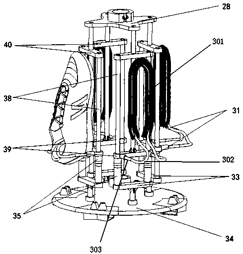
[0016] Example. Inertial centrifugal shoe rack device for shoe washing machine, constituted as figure 1 As shown, including the turntable mechanism, the turntable mechanism is evenly provided with a plurality of shoe rack lower connectors 33, and the two sides of each shoe rack lower connector 33 are distributed with shoe rack slide rails 38, and two shoe rack slide rails 38 are A connecting piece 40 on the shoe rack is provided, a shoe rack slider 39 is arranged between the two shoe rack slide rails 38, and the middle part of the shoe rack slider 39 is provided with a connecting rod running through the connecting piece 33 on the shoe rack, and four connecting rods The upper end of the upper end of the shoe rack is provided with a shoe rack cross connector 28, and the outer part of the shoe rack sl...


PUM


Abstract

The invention discloses an inertial centrifugal shoe rack device for a shoe washing machine. The device comprises a turntable mechanism, the turntable mechanism is evenly provided with a plurality ofshoe rack lower connecting pieces, shoe rack sliding rails are distributed at the two sides of each shoe rack connecting piece, a shoe rack upper connecting piece is arranged on every two shoe rack sliding rails, a shoe rack sliding block is arranged between every two shoe rack sliding rails, connecting rods penetrating through the shoe rack upper connecting pieces are arranged in the middles of the shoe rack sliding blocks, a shoe rack crossed connecting piece is arranged at the upper ends of the four connecting rods, the outer side portion of each shoe rack sliding block is provided with a shoe internal bracket, and a spring is arranged between each shoe rack sliding block and the corresponding shoe rack lower connecting piece; bristles are arranged at the upper portions of the shoe internal brackets. By means of the device, shoes are fixed and cleaned, the cleaning effect is improved, the device can also lift and fall, and therefore the disassembly and assembly of the shoes are facilitated; in addition, the water can be saved, and the use cost is reduced.

Description

technical field [0001] The invention relates to a device for a shoe washing machine, in particular to an inertial centrifugal shoe rack device for a shoe washing machine. Background technique [0002] Shoes are very easy to get dirty and difficult to clean. Scrubbing with bare hands is time-consuming and laborious. It is too expensive to entrust a special shoe washing shop to wash shoes, the scrubbing effect cannot be guaranteed, and it is easy to damage the shoes. Therefore, the problem of shoe cleaning has always been troubled by people. Therefore, special-purpose shoe washing machines have appeared on the market, yet conventional shoe washing machines have the following problems: the position of shoes is not limited in the process of shoe scrubbing, and the spatial position of shoes is random in the scrubbing process, so it is inevitable that some The brushing position is not in place; in addition, the turntable of the conventional shoe washing machine is relatively comm...

Claims


Application Information

Patent Timeline
Patent Type & Authority Applications(China)
IPC IPC(8): A47L23/02
CPCA47L23/02
Inventor 马光何潇洒王敏樑孙智超孙浩岚郑育申允德姜锐
Owner WENZHOU UNIVERSITY
Why Eureka
Try Eureka