Spraying device with powder recycling function

A spraying device and powder technology, applied in the direction of spraying devices, etc., can solve the problems of high spraying cost, inability to be used in time, heavy workload, etc., and achieve the effect of recycling efficiency and recycling quality assurance

Pending Publication Date: 2019-02-15
RES INST OF ZHEJIANG UNIV TAIZHOU
View PDF9 Cites 5 Cited by
  • Summary
  • Abstract
  • Description
  • Claims
  • Application Information

AI Technical Summary

Problems solved by technology

[0002] Since the anti-rust and anti-corrosion effect of powder spraying is far stronger than that of paint spraying, most of the current spraying devices use powder spraying. The spraying tools in the spraying state are generally spray guns. In order to ensure the atomization range of the powder sprayed by the spray gun To be able to fully cover the workpiece to be sprayed, the height needs to be adjusted according to the volume of the workpiece. Therefore, corresponding strip-shaped longitudinal holes will be provided for the spray gun to slide up and down. In the actual spraying process, in order to ensure the spraying efficiency of the workpiece, The spray guns will be relatively distributed. When the workpiece is located between the spray guns on both sides, the spray guns on both sides will spray powder at the same time to fully spray the surface of the workpiece. However, this spraying method will easily cause some powder to fly directly through the strip-shaped longitudinal holes. This situation will not only cause waste of powder, but also cause indoor air pollution. If a worker accidentally inhales a large amount of these powders, it will easily cause harm to personal health.
[0003] The traditional spraying device cannot recover the powder that is not used after spraying, resulting in a large amount of waste of powder, resulting in higher spraying costs. Even if the staff recycles these powders, it is suitable to screen these powders. Sieving out the powder that can be used again is not only a huge workload, but also extremely troublesome. Even if the usable powder is sieved out, it cannot be used in time

Method used


Image

  • Spraying device with powder recycling function
  • Spraying device with powder recycling function
  • Spraying device with powder recycling function

Examples


Embodiment Construction

[0019] Below in conjunction with accompanying drawing and specific embodiment the present invention will be described in further detail:

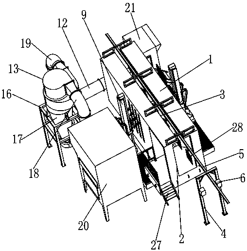
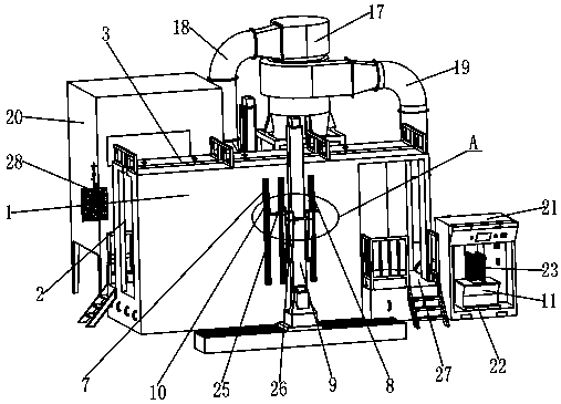
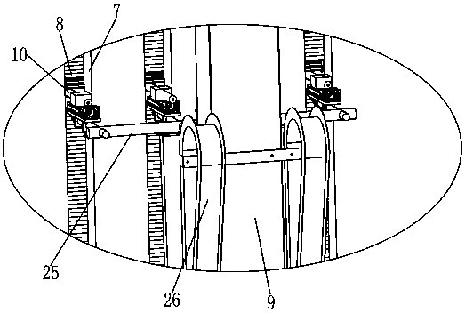
[0020] see Figure 1 to Figure 6 , the present invention provides a spraying device for recyclable powder, comprising a spraying box 1, the left and right side walls of the spraying box 1 are provided with openings 2 communicating with its internal space; the upper and side walls of the spraying box 1 There is a conveying path 3 connected with its internal space; several stands 4 are set up on the left and right sides of the spraying box 1; the hanging conveying chain 5 matching the conveying path 3 is erected on the stand 4; The vertical frame 4 on one side of the spraying box 1 is provided with an induction probe 6; the outer walls of the front and rear sides of the spraying box 1 are provided with some evenly distributed longitudinal slides 7, and the longitudinal slides 7 communicate with the interior of the spraying box 1; The front a...


PUM


Abstract

A spraying device with a powder recycling function comprises a spraying box; the left side wall and the right side wall of the spraying box are provided with openings communicate with the inner spaceof the spraying box; the side wall of the upper side of the spraying box is provided with a conveying channel communicating with the inner space of the spraying box; the left side and the right side of the spraying box are provided with a plurality of vertical frames; the vertical frames are provided with suspension conveying chains matched with the conveying channel; the vertical frame located onone side of the spraying box is provided with inductive probes; the outer walls of the front side and the rear side of the spraying box are provided with a plurality of uniformly-distributed longitudinal slide ways, and the longitudinal slide ways communicate with the interior of the spraying box; the front side and the rear side of the spraying box are provided with symmetrical positioning mechanisms; and the inner walls of the front side and the rear side of the spraying box are spread with organ telescopic plates, and the longitudinal slide ways are blocked and sealed through the organ telescopic plates. Through the spraying device with the powder recycling function, powder sprayed out from a spray gun can be stopped in the spraying device, and moreover, the powder can be recycled.

Description

technical field [0001] The invention relates to a spraying device, in particular to a spraying device in which powder can be recovered and recycled. Background technique [0002] Since the anti-rust and anti-corrosion effect of powder spraying is far stronger than that of paint spraying, most of the current spraying devices use powder spraying. The spraying tools in the spraying state are generally spray guns. In order to ensure the atomization range of the powder sprayed by the spray gun To be able to fully cover the workpiece to be sprayed, the height needs to be adjusted according to the volume of the workpiece. Therefore, corresponding strip-shaped longitudinal holes will be provided for the spray gun to slide up and down. In the actual spraying process, in order to ensure the spraying efficiency of the workpiece, The spray guns will be relatively distributed. When the workpiece is located between the spray guns on both sides, the spray guns on both sides will spray powd...

Claims


Application Information

Patent Timeline
Patent Type & Authority Applications(China)
IPC IPC(8): B05B13/02B05B13/04B05B14/45B05B14/48B05B12/32
CPCB05B12/32B05B13/0264B05B13/041B05B14/45B05B14/48Y02P70/10
Inventor 付彬王蒙张国庆梅武军
Owner RES INST OF ZHEJIANG UNIV TAIZHOU
Why Eureka
Try Eureka