Automatic movement type ladle pouring device

A technology of dumping device and automatic movement, which is applied in the direction of casting molten material container, metal processing equipment, casting equipment, etc., and can solve the problems of workpiece performance difference, increased scrap rate, temperature difference, etc.

Active Publication Date: 2019-02-15
广德亚太汽车智能制动系统有限公司
View PDF15 Cites 9 Cited by
  • Summary
  • Abstract
  • Description
  • Claims
  • Application Information

AI Technical Summary

Problems solved by technology

During the pouring process, it is necessary to change the inclination angle of the ladle so that the molten metal in the ladle is poured into the mold. However, when the liquid metal in one ladle is poured into multiple molds, the existing ladle is in the process of pouring. As the molten metal in the ladle decreases, the inclination of the ladle relative to the vertical direction increases, and the height of the gate of the ladle from the mold decreases, resulting in different temperatures of the molten metal poured into different molds, and each mold The cooling treatment of the inner metal liquid is the same, resulting in differences in the performance of the workpiece and increasing the scrap rate; at the same time, due to the process of the ladle tilting downward, the gate of the ladle gradually moves forward relative to the mold, resulting in When pouring, the position where the molten metal is poured is different, resulting in differences in the performance of the workpiece of each mold

Method used


Image

  • Automatic movement type ladle pouring device
  • Automatic movement type ladle pouring device
  • Automatic movement type ladle pouring device

Examples


Embodiment 1

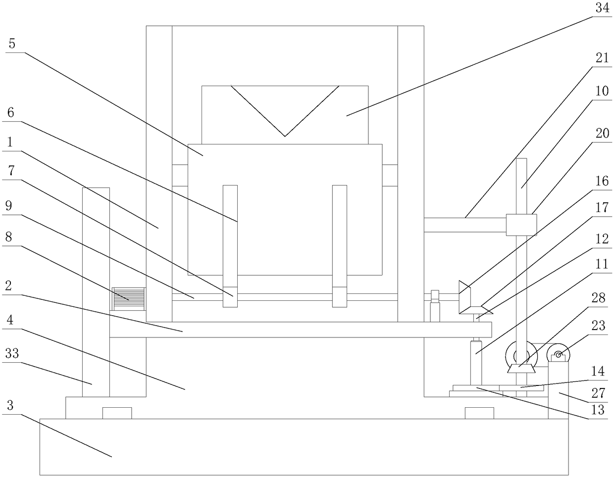
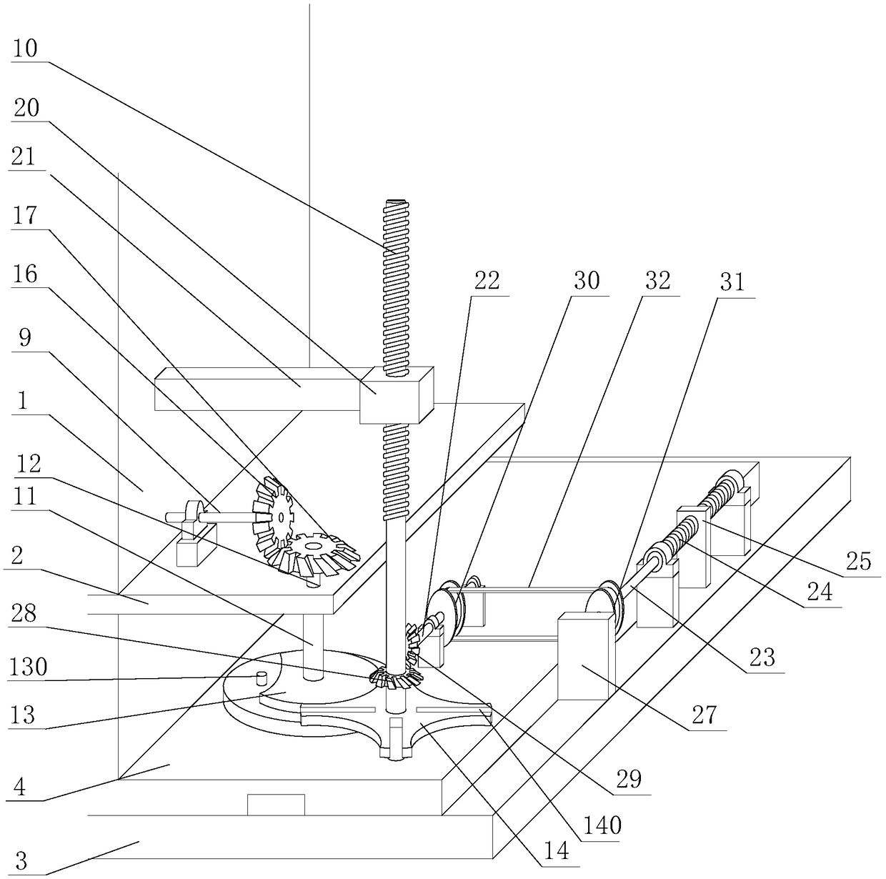
[0038] Such as Figure 1-9 The shown automatic moving ladle dumping device includes a bracket 1, a base 2, a mounting plate 4, a base 3, a fixed frame 5, a ladle 34, a transmission mechanism, a driving part 8, a transverse transmission shaft 9, a Three vertical transmission shafts 10, intermittent transmission assembly, up and down moving slider 20, forward and backward movement mechanism, third longitudinal transmission shaft 24 and front and rear moving slider 25;

[0039]The mounting plate 4 is slidingly installed on the base 3, the base 2 is arranged on the mounting plate 4, the support 1 is vertically fixedly installed on the base 2, the fixed frame 5 is rotatably installed on the support 1 and can rotate up and down relative to the support 1, and the ladle 34 is fixedly connected with the fixed frame 5, the transverse transmission shaft 9 is installed on the bracket 1 and is parallel to the axis of rotation of the fixed frame 5, the original moving part 8 is connected wi...

Embodiment 2

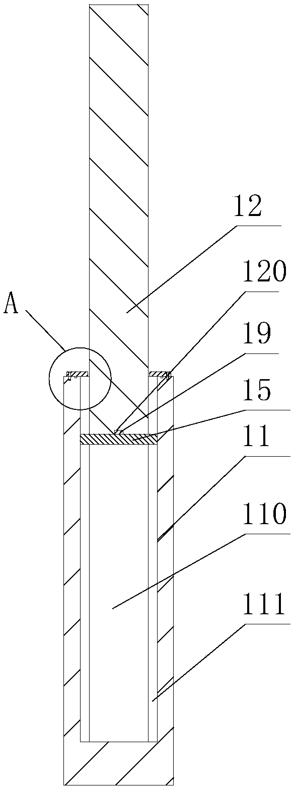
[0075] The difference between this embodiment and the first embodiment is that the first fixing groove 111 and the first mounting hole 110 form a spline groove, and the first fixing bar 15 is an external spline matching the spline groove, so that the connection and transmission are more stable.

Embodiment 3

[0077] The difference between this embodiment and the first embodiment is that the second fixing groove 241 and the second mounting hole 240 form a spline groove, and the second fixing bar 26 is an external spline matching the spline groove, so that the connection and transmission are more stable.


PUM


Abstract

The invention discloses an automatic movement type ladle pouring device comprising a support, a base, an installation plate, a foundation seat, a fixing frame, a ladle, a transmission mechanism, a driving piece, a transverse transmission shaft, a third vertical transmission shaft, an intermittent transmission assembly, a vertical movement sliding block, a front-back movement mechanism, a third longitudinal transmission shaft and a front-back movement sliding block. The installation plate is installed on the foundation seat in a sliding manner and connected with the foundation seat in a slidingmanner. The base is installed on the installation plate. The support is vertically installed on the base. The transverse transmission shaft drives the fixing frame to rotate relative to the support through the transmission mechanism. The vertical movement sliding block drives the support and the base to move up and down relative to the installation plate. The front-back movement mechanism drivesthe installation plate to move front and back relative to the foundation seat. According to the automatic movement type ladle pouring device, in the ladle pouring process, adjustment of the height andthe front-back position of the ladle is achieved, time and effort are saved, and the pouring efficiency is improved.

Description

technical field [0001] The invention relates to the technical field of pouring machinery, in particular to an automatically moving ladle dumping device. Background technique [0002] The ladle is used for pouring in the foundry workshop. After receiving the molten metal in front of the furnace, it is transported to the casting mold by a truck for pouring. It is divided into ladles, ladles, teapot ladles, and ductile iron ladles. During the pouring process, it is necessary to change the inclination angle of the ladle so that the molten metal in the ladle is poured into the mold. However, when the liquid metal in one ladle is poured into multiple molds, the existing ladle is in the process of pouring. As the molten metal in the ladle decreases, the inclination of the ladle relative to the vertical direction increases, and the height of the gate of the ladle from the mold decreases, resulting in different temperatures of the molten metal poured into different molds, and each mo...

Claims


Application Information

Patent Timeline
Patent Type & Authority Applications(China)
IPC IPC(8): B22D41/06
CPCB22D41/06
Inventor 周技陈青陆青青
Owner 广德亚太汽车智能制动系统有限公司
Why Eureka
Try Eureka