Push-pull opening and closing mechanism used for power line sensor and having locking and limiting functions

A technology of opening and closing mechanism and pulling mechanism, which is applied to hand-held tools, manufacturing tools, etc., can solve the problems of reducing equipment reliability, complex structure, and inability to rigidly lock, and achieves simple operation, simple structure, and high reliability. Effect

Pending Publication Date: 2019-02-15
北京则拓科技有限责任公司
View PDF5 Cites 2 Cited by
  • Summary
  • Abstract
  • Description
  • Claims
  • Application Information

AI Technical Summary

Problems solved by technology

[0013] In order to improve the deficiencies of the existing open-close type power line sensor open-close mechanism, such as time-consuming and labor-intensive operation, complicated structure that reduces equipment reliability, inability to rigidly lock and reduce measurement reliability, etc., the present invention provides a push-pull open-close mechanism with locking limit In operation, the opening and closing of the mechanism is only realized by simple push-pull movement. The mechanism is simple in composition and has the function of locking and limiting, which can realize the reliable locking of the opening and closing mechanism, and can realize the effective limit of the movement range and trajectory of the opening and closing mechanism.

Method used


Image

  • Push-pull opening and closing mechanism used for power line sensor and having locking and limiting functions
  • Push-pull opening and closing mechanism used for power line sensor and having locking and limiting functions
  • Push-pull opening and closing mechanism used for power line sensor and having locking and limiting functions

Examples


Embodiment Construction

[0038] The technical solution of the present invention will be further described below in conjunction with the accompanying drawings.

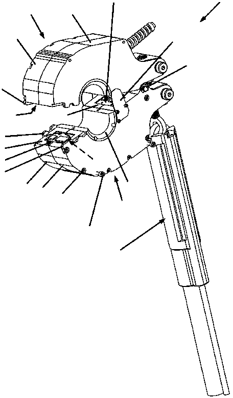
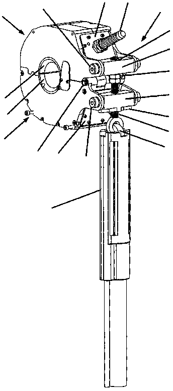
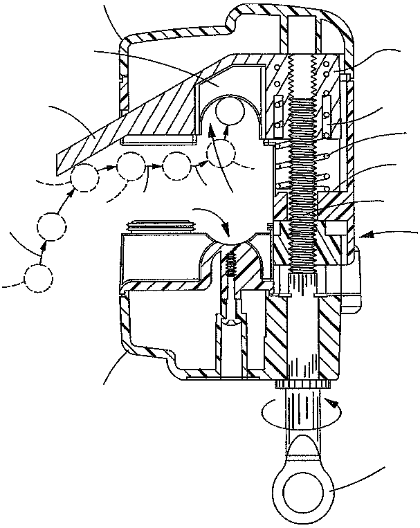
[0039] Such as Figure 12-13 As shown, the technical solution adopted in the present invention is a push-pull opening and closing mechanism with a locking limit, including a first semi-annular housing 101, a second semi-annular housing 102, a rotating shaft 103, a slide plate 104 and a ring groove shape Mounting mechanism 105 .

[0040] The first semi-annular housing 101 and the second semi-annular housing 102 are provided with a first circular hole 201, and the annular groove-shaped mounting mechanism 105 is provided with a second circular hole 401, and the first circular hole 201 and the second circular The hole 401 is used to pass through the rotating shaft 103 , and the first semi-annular housing 101 and the second semi-annular housing 102 can rotate around the rotating shaft 103 . When the first semi-annular housing 101 and the second s...


PUM


Abstract

The invention discloses a push-pull opening and closing mechanism used for a power line sensor and having locking and limiting functions. The push-pull opening and closing mechanism used for the powerline sensor and having the locking and limiting functions comprises a first semicircular shell, a second semicircular shell, a rotary shaft, a sliding plate and an annular groove-shaped installationmechanism. The first semicircular shell and the second circular shell are installed on the annular grooves-shaped installation mechanism through the rotary shaft, and the rotating ranges of the firstsemicircular shell and the second circular shell are limited by the annular groove-shaped installation mechanism. Sliding plates are mounted in sliding grooves in the two sides of the annular groove-shaped installation mechanism. The sliding plates can be pushed and pulled to move upwards and downwards so as to close and open the first semicircular shell and the second semicircular shell. Limitingmechanisms are arranged on the sliding plates and are used for limiting the moving ranges of the sliding plates. Stop mechanisms of the annular groove-shaped installation mechanism can be combined with concave parts on the sliding plates so as to keep the first semicircular shell and the second semicircular shell in a locked state. The push-pull opening and closing mechanism is easy and convenient to operate, simple in structure and capable of achieving reliable locking and effective limiting.

Description

technical field [0001] The invention relates to a switchable power line sensor, in particular to a switch mechanism for safely placing power line measuring equipment and other electronic equipment on the power line of a grid. Background technique [0002] Electricity has become one of the most important energy supply methods in modern society, and the grid power line is the channel for power transmission. In order to ensure the normal operation of the power grid and continuously and reliably transmit power, it is necessary to monitor the current, voltage and other electrical quantities on the power lines of the power grid to understand the operating status of the power lines of the power grid, find problems in the operation process, and eliminate hidden dangers in time. When a fault occurs during the operation of the power line of the power grid, the evolution process of the fault can be analyzed by recording the change of the electrical quantity during the fault process. L...

Claims


Application Information

Patent Timeline
Patent Type & Authority Applications(China)
IPC IPC(8): B25B27/00
CPCB25B27/00
Inventor 唐先武
Owner 北京则拓科技有限责任公司
Why Eureka
Try Eureka