Factory machine component classifying storage box

A technology for mechanical parts and storage boxes, applied in the field of storage boxes, can solve problems such as difficulty in finding mechanical parts, different sizes of mechanical parts, affecting use, etc., to achieve the effect of facilitating storage and improving use requirements

Inactive Publication Date: 2019-02-15
长兴曼尔申机械科技有限公司
View PDF0 Cites 3 Cited by
  • Summary
  • Abstract
  • Description
  • Claims
  • Application Information

AI Technical Summary

Problems solved by technology

[0002] A box is a square utensil for collecting items, usually used to store items. Some mechanical parts are often manufactured in factories. Mechanical parts, also known as mechanical components, are the basic components of machinery. They are inseparable individual parts that make up machinery and machines. There are many different sizes, and storage boxes are needed to store them. The existing factory machinery parts storage boxes cannot meet people's needs, so more factory machinery parts storage boxes with multiple classifications are needed; the existing factory machinery parts storage boxes There are certain disadvantages when using the storage box. First of all, the parts storage box cannot store a variety of mechanical parts, making different mechanical parts messy, making it difficult to find the mechanical parts that need to be used, which increases the time cost of taking mechanical parts , Secondly, it is impossible to effectively classify the storage boxes, which affects the use. Finally, it is impossible to achieve convenient mobile storage boxes. Therefore, we propose a sorted storage box for factory mechanical parts

Method used


Image

  • Factory machine component classifying storage box
  • Factory machine component classifying storage box
  • Factory machine component classifying storage box

Examples


Embodiment Construction

[0025] In order to make the technical means, creative features, goals and effects achieved by the present invention easy to understand, the present invention will be further described below in conjunction with specific embodiments.

[0026] In the description of the present invention, it should be noted that the terms "upper", "lower", "inner", "outer", "front end", "rear end", "both ends", "one end", "another end" The orientation or positional relationship indicated by etc. is based on the orientation or positional relationship shown in the drawings, and is only for the convenience of describing the present invention and simplifying the description, rather than indicating or implying that the referred device or element must have a specific orientation, use a specific Azimuth configuration and operation, therefore, should not be construed as limiting the invention. In addition, the terms "first" and "second" are used for descriptive purposes only, and should not be understood ...


PUM


Abstract

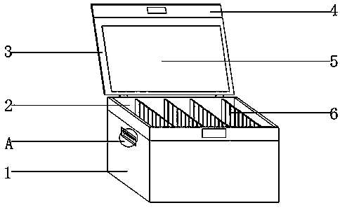
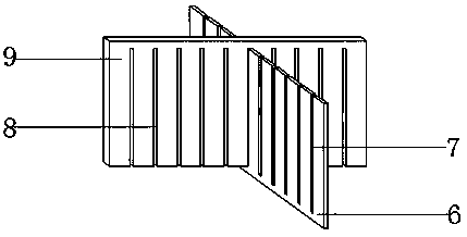
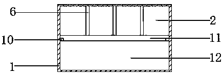
The invention discloses a factory machine component classifying storage box. The factory machine component classifying storage box comprises a storage box shell. The position, close to the rear side,of the upper end of the storage box shell is connected with a box cover through a hinge. The upper end of the box cover is connected with an overturning plate. A storage bag is arranged at the middleposition of the front end of the box cover. A hollow structure formed between the storage bag and the box cover is a storage bin. A second concave groove is formed in one side of the storage box shell, a lifting rope installing block is arranged at the upper portion of the groove bottom of the second concave groove, and an installing hole is formed in the upper end of the lifting rope installing block. According to the factory machine component classifying storage box, a first partition plate, a second partition plate, a first clamping groove, a second clamping groove, a third partition plate,the lifting rope installing block and the storage bag are arranged, random component storage bin combination can be conducted according to the component size, the storage box can be subjected to up-down layering, connection of a lifting rope and other rope objects can be achieved, drawing and other paper objects can be conveniently stored, certain practicability is achieved, and better usage prospects are brought.

Description

technical field [0001] The invention relates to the field of storage boxes, in particular to a classified storage box for factory machinery parts. Background technique [0002] A box is a square utensil for collecting items, usually used to store items. Some mechanical parts are often manufactured in factories. Mechanical parts, also known as mechanical components, are the basic components of machinery. They are inseparable individual parts that make up machinery and machines. There are many different sizes, and storage boxes are needed to store them. The existing factory machinery parts storage boxes cannot meet people's needs, so more factory machinery parts storage boxes with multiple classifications are needed; the existing factory machinery parts storage boxes There are certain disadvantages when using the storage box. First of all, the parts storage box cannot store a variety of mechanical parts, making different mechanical parts messy, making it difficult to find the ...

Claims


Application Information

Patent Timeline
Patent Type & Authority Applications(China)
IPC IPC(8): B25H3/02
CPCB25H3/022
Inventor 钱月方
Owner 长兴曼尔申机械科技有限公司
Why Eureka
Try Eureka