Anchor chain stopper for ocean anchoring

An anchor chain chain maker and mooring technology, which is applied to ships and other directions, can solve the problems of damage to transmission parts, large anchor and anchor chain force, and large working load of the windlass, so as to improve the firmness, high firmness, good stability

Active Publication Date: 2019-02-15
SUZHOU LVDIAN INFORMATION TECH CO LTD
View PDF8 Cites 3 Cited by
  • Summary
  • Abstract
  • Description
  • Claims
  • Application Information

AI Technical Summary

Problems solved by technology

[0004] The invention provides a chain stopper for marine mooring, which has the advantages of good stability, high firmness, low energy consumption, convenient use and simple operation. The single chain link arranged horizontally or vertically in the center is compressed and fixed, but when the single chain link on the anchor chain does not match the position of the splint on the chain stopper, it will cause the anchor after clamping to be fixed. The chain slips and loosens under various forces, causing various forces on the anchor and the anchor chain to be directly transmitted to the windlass and causing damage to it, so that the chain stopper cannot fix the anchor chain and protect it. The function of the windlass, so when fixing the anchor chain, it is necessary to repeatedly start the windlass to adjust the horizontal or vertical arrangement of the single chain link in the anchor chain to the splint of the chain stopper. It takes a lot of time and electric energy to anchor the chain, and because the force of the anchor and the anchor chain is large, the working load of the windlass is relatively large. When the windlass is started repeatedly in a short period of time, it will damage The transmission parts cause severe impact, which causes damage to the transmission parts inside the windlass, thus seriously affecting the service life of the windlass

Method used


Image

  • Anchor chain stopper for ocean anchoring
  • Anchor chain stopper for ocean anchoring
  • Anchor chain stopper for ocean anchoring

Examples


Embodiment Construction

[0024] The following will clearly and completely describe the technical solutions in the embodiments of the present invention with reference to the accompanying drawings in the embodiments of the present invention. Obviously, the described embodiments are only some, not all, embodiments of the present invention. Based on the embodiments of the present invention, all other embodiments obtained by persons of ordinary skill in the art without making creative efforts belong to the protection scope of the present invention.

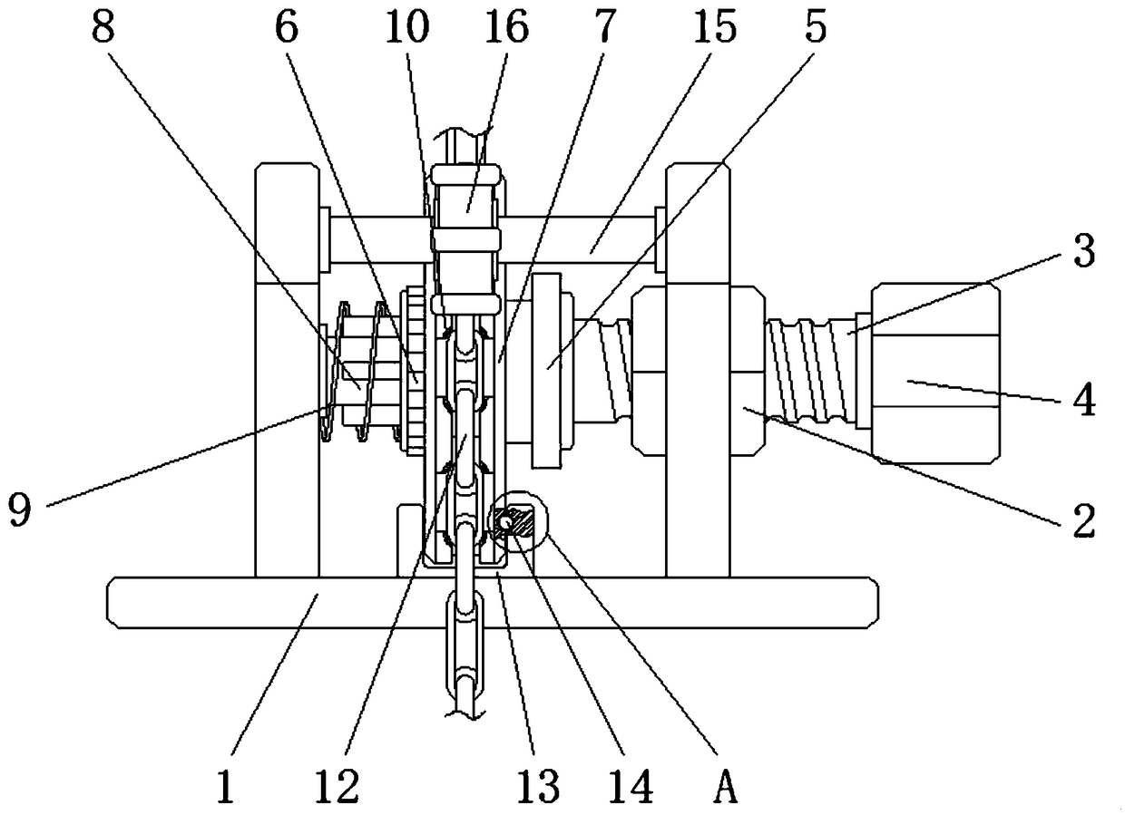
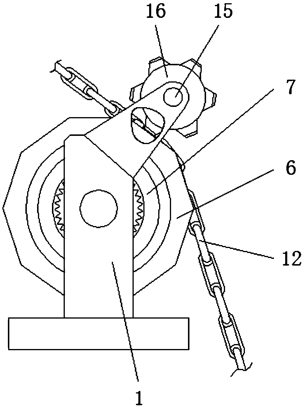
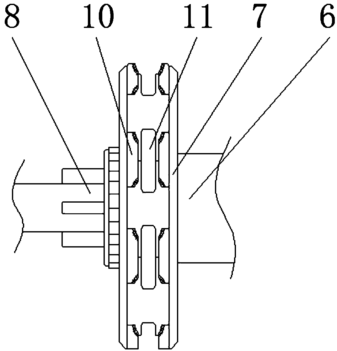
[0025] see Figure 1-6 , an anchor chain stopper for marine mooring, comprising a fixed bracket 1, a locking nut 2 is fixedly installed inside one side of the fixing bracket 1, and a locking connecting rod 3 is connected to the inner thread of the locking nut 2, and the locking connecting rod 3 One end of the rod 3 is provided with a hexagonal adjusting head 4, and the other end of the locking connecting rod 3 is fixedly installed with a thrust bearing 5, one ...


PUM


Abstract

The invention relates to the technical field of ocean engineering equipment and discloses an anchor chain stopper for ocean anchoring. The anchor chain stopper for ocean anchoring comprises a fixing bracket; a locking nut is fixedly mounted in one side of the fixing bracket; a locking connecting rod is connected to an internal thread of the locking nut; a hexagon adjustment head is arranged at oneend of the locking connecting rod; a thrust bearing is fixedly mounted at the other end of the locking connecting rod; a locking gear is arranged on one side of the thrust bearing; and a locking chain wheel fixedly sleeves one side of the external surface of the locking gear. According to the anchor chain stopper for ocean anchoring, as a rubber material friction cushion block on a clamping blockis arranged, an anchor chain can be more effectively clamped on a locking chain wheel so that a phenomenon that chain links on the locking chain wheel are loose due to the shaking of a hull cannot becaused, and a windlass is further prevented from being damaged because a force generated by an anchor and the anchor chain directly acts upon the windlass; and therefore, the stability of the chain stopper during fixing the anchor chain is effectively improved.

Description

technical field [0001] The invention relates to the technical field of marine engineering equipment, in particular to an anchor chain stopper for marine mooring. Background technique [0002] The chain stopper is a kind of anchor chain fixing device installed between the windlass and the anchor chain barrel on the ship. It is mainly used to fix the anchor chain and prevent the anchor chain from sliding down. It is directly transmitted to the hull to reduce the load of the windlass and protect the windlass. However, since the anchor chain is spliced ​​by chain links arranged horizontally and vertically, the existing chain stoppers, whether they are spiral or knife Both have the following disadvantages: [0003] The existing chain stoppers only use splints to compress and fix the single chain link arranged horizontally or vertically in the anchor chain, but when the single link on the anchor chain does not match the position of the splint on the chain stopper When clamping, ...

Claims


Application Information

Patent Timeline
Patent Type & Authority Applications(China)
IPC IPC(8): B63B21/18
CPCB63B21/18
Inventor 不公告发明人
Owner SUZHOU LVDIAN INFORMATION TECH CO LTD
Why Eureka
Try Eureka