Ball loading device

A ball and automatic feeding technology, which is applied in the directions of loading/unloading, transportation and packaging, conveyors, etc., can solve the problems of affecting the follow-up steps, ball jamming, etc., and achieve labor cost saving, fast ball conveying speed and simple structure Effect

Inactive Publication Date: 2019-02-15
东莞市国森科精密工业有限公司
View PDF7 Cites 2 Cited by
  • Summary
  • Abstract
  • Description
  • Claims
  • Application Information

AI Technical Summary

Problems solved by technology

[0003] However, the traditional feeding mechanism has no way to ensure that the balls can be delivered quickly, and there is no way to keep the balls in a straight line during the transportation process, so that the balls contact each other and affect the subsequent steps, and the balls are easy to gather and the balls are stuck in the transportation channel.

Method used


Image

  • Ball loading device
  • Ball loading device

Examples


Embodiment Construction

[0013] The present invention will be further elaborated below in conjunction with accompanying drawing:

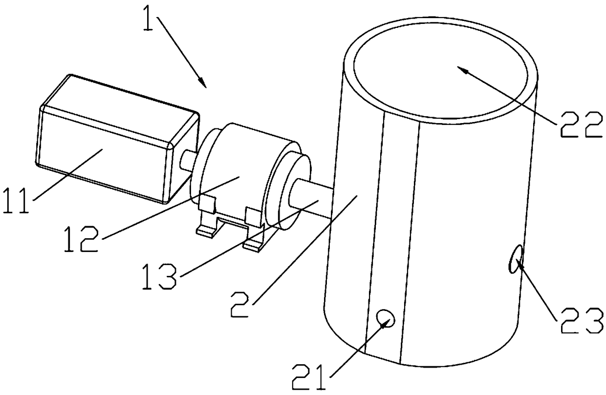
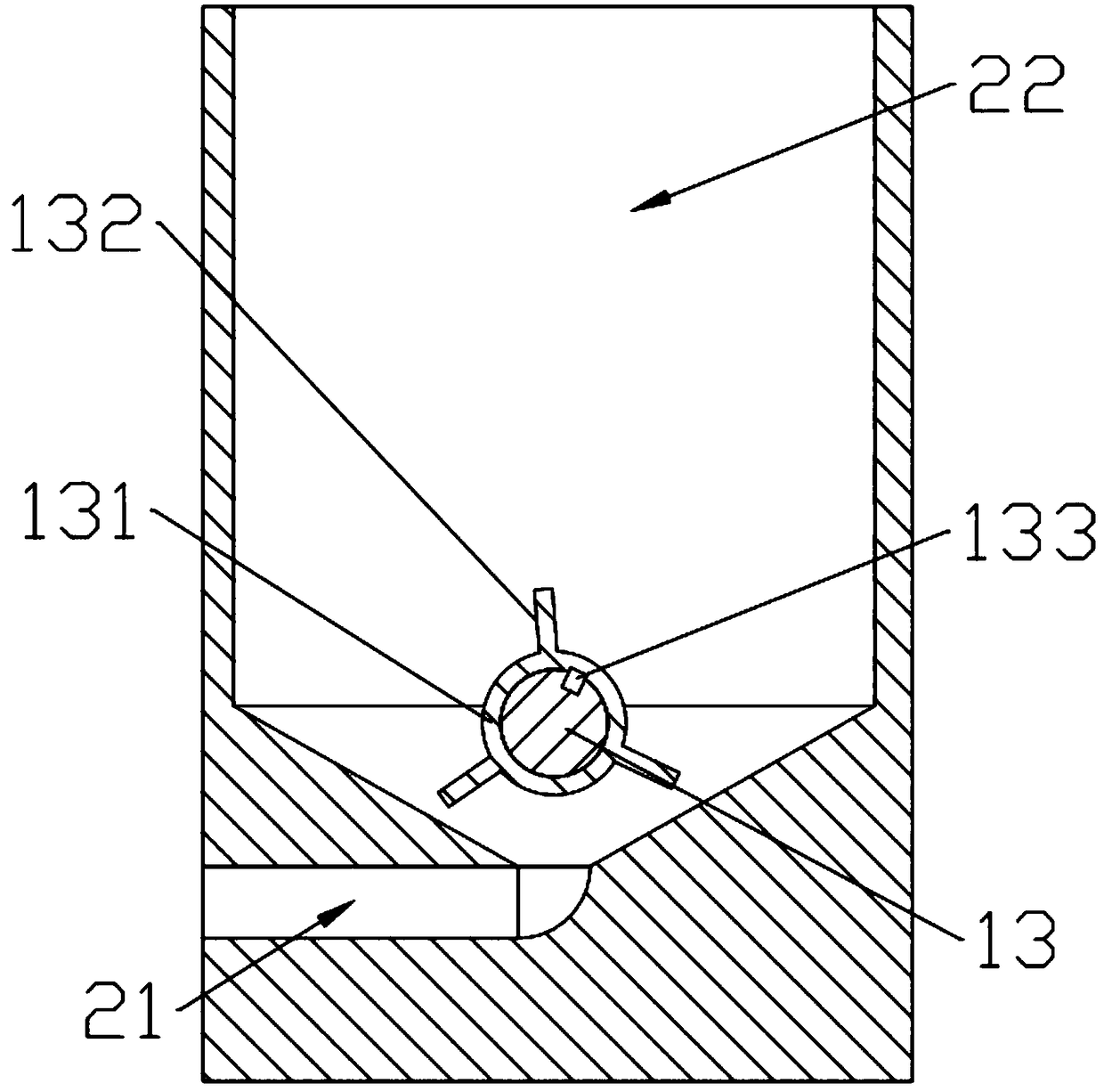
[0014] Such as figure 1 with figure 2 As shown, a ball automatic feeding device includes a feeding cylinder 2 and a driving mechanism 1. The driving mechanism 1 includes a driving motor 11, a reducer 12 and an output shaft 13. The output end of the driving motor 11 is connected to the reducer 12 in rotation. , the output end of the reducer 12 forms a rotational connection with the output shaft 13, the output shaft 13 is placed in the upper material cylinder 1, the upper material cylinder 2 is funnel-shaped, and the upper material cylinder 2 includes a material storage chamber 22 and an output channel 21, the material storage The cavity 22 and the output channel 21 are located in the upper material cylinder 2, the material storage cavity 22 communicates with the output channel 21, the output channel 21 communicates with the outside, the upper material cylinder 1 is provid...


PUM


Abstract

The invention relates to an automatic ball loading device. The ball loading device comprises a loading cylinder and a driving mechanism; the loading cylinder comprises a storage cavity and an output channel; the storage cavity and the output channel are positioned in the loading cylinder; the storage cavity communicates with the output channel; the output channel communicates with the external; the driving mechanism comprises a driving motor, a speed reducer and an output shaft; an output end of the driving motor is rotationally connected with the speed reducer; an output end of the speed reducer is rotationally connected with the output shaft; the output shaft penetrates through the loading cylinder; and a stirring wheel is arranged on the output shaft, and is aligned to the output channel. The ball loading device is simple in structure, convenient to assemble, higher in ball conveying speed and easy to enable balls to linearly move, cannot cause collision between the balls to preventinfluence on subsequent steps, meanwhile, saves the labor cost, and cannot block the balls in the output channel.

Description

technical field [0001] The invention relates to a ball feeding device, in particular to a ball feeding device in the field of ball processing and testing. Background technique [0002] As one of the important components of bearings, balls are generally detected manually through a dial indicator. In order to improve the detection speed, unqualified products are generally sorted out according to the inclined table and the baffle, and during the processing It is also necessary to process the balls one by one. The feeding device in the detection and processing process is mainly composed of a hopper, a feeding trough, and a feeding mechanism. Sequentially sent into the feeding trough, and then sent to the processing position or detection mechanism on the machine tool by the feeding mechanism. [0003] However, the traditional feeding mechanism has no way to ensure that the balls can be delivered quickly, and there is no way to keep the balls in a straight line during the transpo...

Claims


Application Information

Patent Timeline
Patent Type & Authority Applications(China)
IPC IPC(8): B65G65/48
CPCB65G65/4881B65G2201/042
Inventor 杨学政
Owner 东莞市国森科精密工业有限公司
Why Eureka
Try Eureka