A pile-forming simulation device for indoor solidified piles
What is AI technical title?
AI technical title is built by Patsnap AI team. It summarizes the technical point description of the patent document.
A simulation device and internal curing technology, applied in the field of geotechnical engineering, can solve the problems of inappropriate curing agent and construction technology, and achieve the effect of reducing design defects and small size
Active Publication Date: 2020-08-18
KUNMING UNIV OF SCI & TECH
View PDF5 Cites 0 Cited by
Summary
Abstract
Description
Claims
Application Information
AI Technical Summary
This helps you quickly interpret patents by identifying the three key elements:
Problems solved by technology
Method used
Benefits of technology
Problems solved by technology
[0004] The purpose of the present invention is to provide a pile-forming simulation device for indoor curing of piles, to solve the problems of unsuitable curing agent and construction technology for soft soil curing in engineering practice, to predict the strength of soft soil after curing in advance, and to make engineering The actual data is more sufficient
Method used
Image
Click on the blue label to locate the original text in one second.
Reading with bidirectional positioning of images and text.
Examples
Embodiment 1
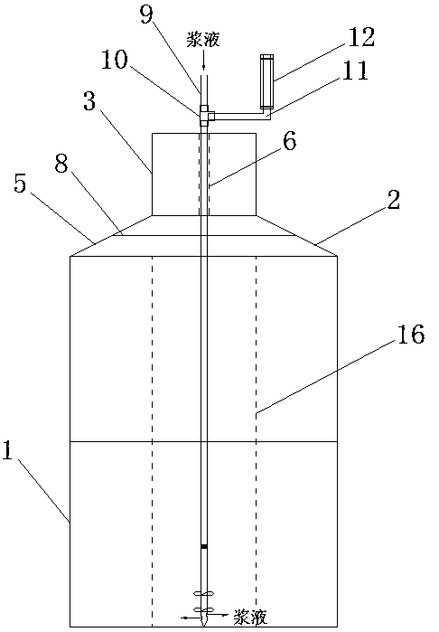
[0028] Embodiment 1: as Figure 1~5 As shown, a pile-forming simulation device for indoor curing piles, including brackets, stirring components, test chamber components and injection pumps;
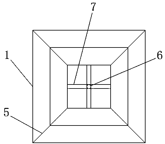
[0029] The bracket includes a bracket I1, a bracket II2, a bracket III3, a limit tube 6, and a support rod 7. Both the bracket I1 and the bracket III3 are hollow cuboid structures, and the bracket II2 is located between the bracket I1 and the bracket III3. The support II2 includes four oblique rods 5, and the four oblique rods 5 fixedly connect the four apexes at the top of the support I1 with the four apexes at the bottom of the support III3. , two support rods 7 are fixed vertically, and the intersection of two horizontal and two vertically fixed support rods 7 is a rectangular gap, and the limit tube 6 is a hollow cylindrical tube, the top of the limit tube 6, The bottom ends are respectively fixed at the intersection of the horizontal and vertical fixed support rods 7 on the upper an...
Embodiment 2
[0035] Embodiment 2: The structure of this embodiment is the same as that of Embodiment 1, except that a protrusion is provided on the rocker 11 to limit the vertical displacement of the handle.
[0036] The specific operation steps of the pile-forming simulation device of the indoor solidified pile body in this embodiment are as follows:
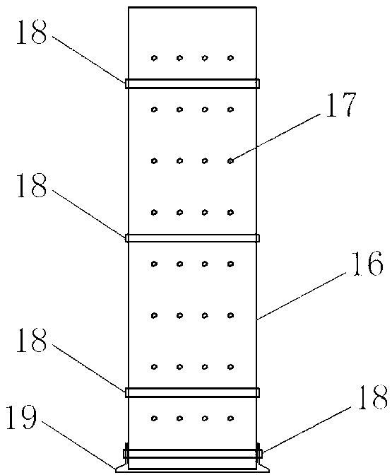
[0037] Put the test box on the base 19, put the clamp 18 on it, cut a sufficient amount of soil samples from the undisturbed soil samples according to the engineering requirements, place them in the test box 16 and compact them in layers, adjust the positions of the base 19 and the drill bit 20, and determine Hole position (1, 2, 3), code the pile number (1, 2, 3), hole number (1, 2, 3), serial number (1, 2, 3);
[0038] Construction of mixing piles: Stake out pile position "1", determine the specific pile position; drill bit 4 is in place, check the length of drill pipe 13, the diameter of drill bit 4, move drill bit 4 to the designated po...
PUM
Abstract
The invention discloses a pile formation simulator used for an indoor cured pile body. The pile formation simulator used for the indoor cured pile body comprises a support, a stirring component, a test box component and an injection pump. The test box component is located on the lower portion of the interior of the support. The stirring component is located above the test box component. The support comprises a support body I, a support body II, a support body III, a limiting tube and a supporting rod. The stirring component comprises a grouting pipe, a three-way pipe, a rocker, a handle, a drill stem, blades, a grout jet port and a drill bit. The text box component comprises a test box, one or more clamps and a base. The pile formation simulator is small in size and capable of truly simulating the cured pile body indoors in engineering practice. By adoption of the pile formation simulator, the problems that in the prior art, a large quantity of materials are needed for curing the pilebody in engineering practice, and environmental pollution is likely to be caused are solved; and by adoption of the pile formation simulator, a better curing agent formula can be worked out, a large quantity of reliable data are provided for engineering practice, and engineering design defects caused by insufficient data are greatly reduced.
Description
technical field [0001] The invention relates to a pile-forming simulation device for an indoor solidified pile body, belonging to the field of geotechnical engineering. Background technique [0002] Various soft soils are widely distributed in my country, and their main characteristics are high natural moisture content, high compressibility, low shear strength, low water permeability, thixotropy and rheology. Soft soil has obvious structural properties, once disturbed, its strength will be significantly reduced, and it has obvious rheological properties, which can produce large secondary consolidation settlement. Buildings on soft soil foundations have a large amount of settlement and a long time for settlement stability. The engineering nature of soft soil is quite special. If it is not treated or handled properly during construction, a series of problems such as building cracking, house collapse, and building tilt will often occur due to the settlement of the building fou...
Claims
Application Information
Patent Timeline
Application Date:The date an application was filed.
Publication Date:The date a patent or application was officially published.
First Publication Date:The earliest publication date of a patent with the same application number.
Issue Date:Publication date of the patent grant document.
PCT Entry Date:The Entry date of PCT National Phase.
Estimated Expiry Date:The statutory expiry date of a patent right according to the Patent Law, and it is the longest term of protection that the patent right can achieve without the termination of the patent right due to other reasons(Term extension factor has been taken into account ).
Invalid Date:Actual expiry date is based on effective date or publication date of legal transaction data of invalid patent.

