Light partition wall

A light-weight, light-weight steel keel technology, applied to walls, building components, buildings, etc., can solve the problems of cumbersome manufacturing or installation, heavy workload, etc.

Pending Publication Date: 2019-02-15
王工一
View PDF0 Cites 1 Cited by
  • Summary
  • Abstract
  • Description
  • Claims
  • Application Information

AI Technical Summary

Problems solved by technology

[0002] The existing indoor partition walls usually use brick partition walls and traditional methods of making l

Method used


Image

  • Light partition wall
  • Light partition wall
  • Light partition wall

Examples


Embodiment Construction

[0025] In order to make the object, technical solution and advantages of the present invention clearer, the present invention will be further described in detail below in conjunction with the accompanying drawings.

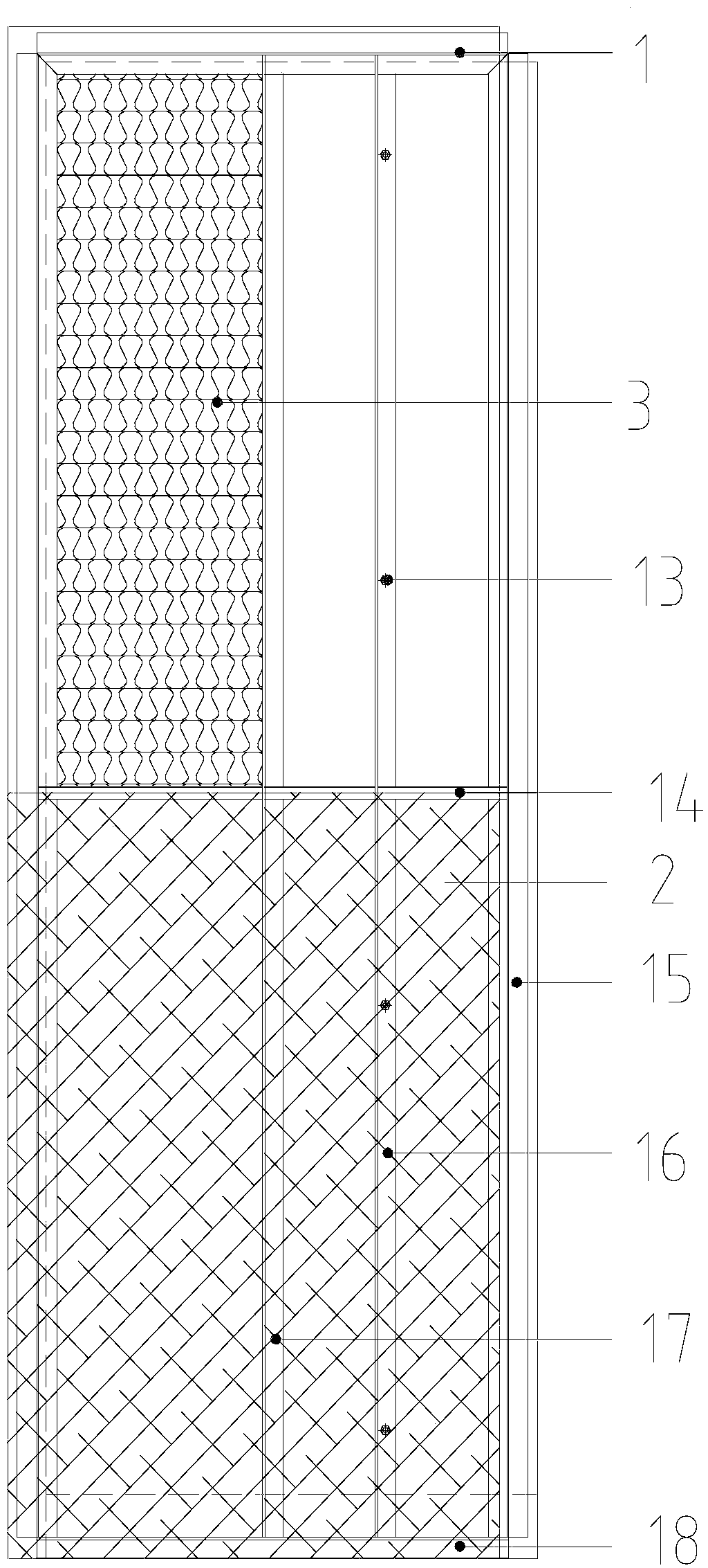
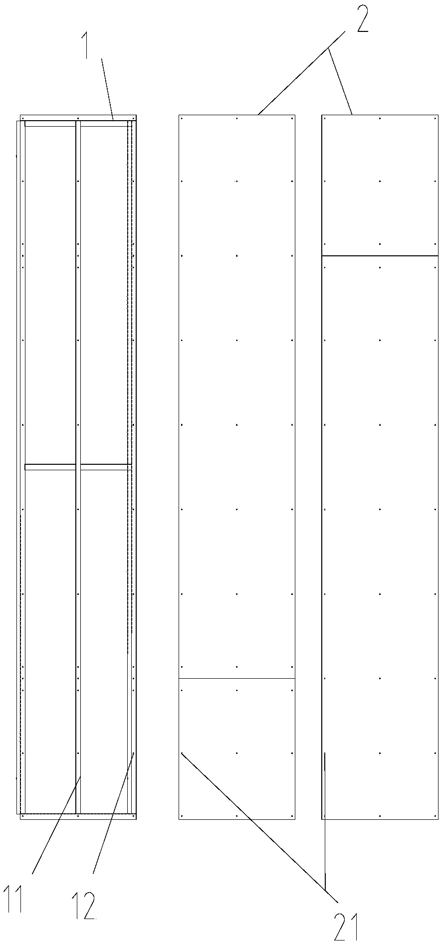
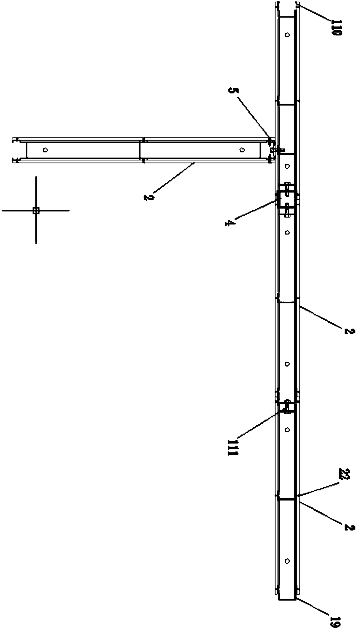
[0026] The lightweight partition wall disclosed by the present invention, such as figure 1 , figure 2 , image 3 As shown, including the standard formwork, the standard formwork is rectangular, the standard formwork includes light steel keel 1 and panel 2, there are two panels 2, light steel keel 1 is located between the two panels, panel 2 and light steel keel 1 are connected by bolts The two opposite sides of the light steel keel 1 are provided with superimposed parts that can cooperate with each other. The superimposed part on one side is the large end 120, and the superimposed part on the other end is the small end 119. The panel 2 does not cover the small part of the superimposed part. End 119, the inside of the standard formwork is filled with mineral woo...


PUM


Abstract

The invention discloses a light partition wall, which comprises standard formworks. Each standard formwork comprises a light steel keel and two face plates, wherein the light steel keel is located between the two face plates; the face plates and the light steel keels are connected through bolts; the two opposite edges of the light steel keels are provided with overlaid parts which can be mutuallymatched; and the face plates do not cover the small ends of the overlaid parts. The light partition wall achieves the purposes that the light partition wall can replace a bricked partition wall and atraditional light steel keel partition wall manufactured on a field, assembling is convenient and quick, labor force is saved, and the construction and production efficiency is improved; and meanwhilethe house space is saved.

Description

technical field [0001] The invention relates to the field of construction, in particular to a lightweight partition wall. Background technique [0002] The existing indoor partition wall usually adopts brick partition wall and the traditional method of making light steel keel partition wall on site, which is cumbersome to manufacture or install, and the workload is heavy. Contents of the invention [0003] The present invention aims to provide a lightweight partition wall, which can replace brick partition walls and traditional on-site light steel keel partition walls. It is convenient and quick to assemble, saves labor, improves construction production efficiency, and saves room space. [0004] In order to achieve the above object, the present invention is achieved by adopting the following technical solutions: [0005] The lightweight partition wall disclosed by the present invention includes a standard formwork, the standard formwork includes a light steel keel and a p...

Claims


Application Information

Patent Timeline
IPC IPC(8): E04B2/74E04B2/76E04B2/78E04B2/82
CPCE04B2/74E04B2/7414E04B2/7457E04B2/76E04B2/78E04B2/821
Inventor 王工一
Owner 王工一
Why Eureka
Try Eureka