
Absorber-resistant latch system provided with vibration absorber

A shock absorber and shock-resistant technology, which is applied in the field of door latches, can solve the problems of complex structure of shock-absorbing equipment and reduced flexibility of door opening and closing

Inactive Publication Date: 2019-02-15
余祝明
View PDF0 Cites 2 Cited by
  • Summary
  • Abstract
  • Description
  • Claims
  • Application Information

AI Technical Summary

Problems solved by technology

[0002] A door refers to the entrance and exit of a building or a device that can be opened and closed at the entrance and exit. A door is an entity that divides a limited space. Its function is to connect and close the entrances and exits of two or more spaces. The door is usually equipped with a latch. The door bolt is inserted into the door so that the door cannot be pushed open. The door bolt is a locking device for the door body. The door bolt is generally divided into automatic or manual. At present, the automatic door bolt is usually installed on the upper side of the door frame, and the door is locked by contact with the door body. However, in the prior art, the automatic door bolt is usually exposed on the door frame, so that the door can only be opened and closed on one side of the door bolt, thereby reducing the flexibility of opening and closing the door. The door and the door bolt need to be in slow contact to increase the safety of the door. service life, but the structure of the damping device for the door in the prior art is complicated, therefore, the door latch needs to be improved

Method used


Image

  • Absorber-resistant latch system provided with vibration absorber
  • Absorber-resistant latch system provided with vibration absorber
  • Absorber-resistant latch system provided with vibration absorber

Examples


Embodiment Construction

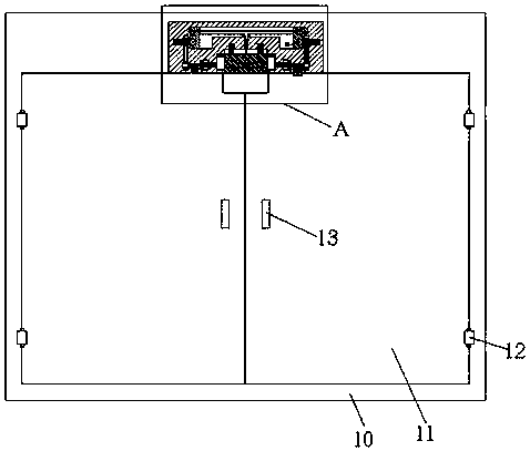
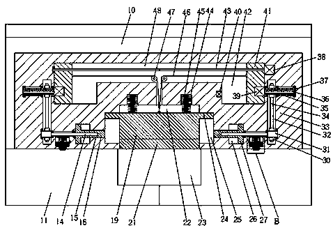
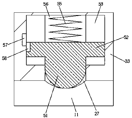
[0020] Combine below Figure 1-4 The present invention is described in detail, and for convenience of description, the orientations mentioned below are now stipulated as follows: figure 1 The up, down, left, right, front and back directions of the projection relationship itself are the same.

[0021] refer to Figure 1-4 According to an embodiment of the present invention, the shockproof bolt system with a shock absorber includes a door frame body 10, and the left and right sides of the door frame body 10 are hingedly installed by two hinge shafts 12, which can be pushed backward or pulled forward respectively. The two door bodies 11 also include a bolt main body 33 arranged in the door frame body 10 on the upper side of the door body 11. A sliding space 22 is opened in the bottom end surface of the door bolt main body 33, and a sliding space 22 is opened in the sliding space 22. A locking unit that can protrude from the bottom end surface of the door bolt main body 33 is in...


PUM


Abstract

The invention discloses an absorber-resistant latch system provided with a vibration absorber. The system comprises a door frame, wherein two door bodies which can be backwards pushed or forwards pulled are correspondingly mounted at the inner left side and the inner right side of the door frame body by hinging through two hinging shafts. The system further comprises door latch bodies which are arranged in the door frame at the upper parts of the door bodies; sliding spaces are formed in the bottom end surfaces of the door latch bodies; locking units which can extend of the bottom end surfaces of the door latch bodies are mounted in the sliding spaces, and the locking units can be completely pulled into the sliding spaces through power pulling devices; the power pulling devices are connected to reinforcing devices in a spline fitting manner; the reinforcing devices are used for reinforcing the locking units, and the locking units can be firmly clamped into concave locking ports in thetop end surfaces of the door bodies. The system further comprises vibration absorbing mechanisms which are arranged in the bottom end surfaces of the door latch bodies at the left side and the rightsides of the locking units, and the vibration absorbing positioning mechanisms are in clamping bucking connection with arc-shaped concave ports in the top end surfaces of the door bodies.

Description

technical field [0001] The invention relates to the technical field of door latches, in particular to an anti-shock latch system with a shock absorber. Background technique [0002] A door refers to the entrance and exit of a building or a device installed at the entrance and exit that can be opened and closed. A door is an entity that divides a limited space. Its function is to connect and close the entrances and exits of two or more spaces. The door is usually equipped with a latch. The door bolt is inserted into the door so that the door cannot be pushed open. The door bolt is a locking device for the door body. The door bolt is generally divided into automatic or manual. At present, the automatic door bolt is usually installed on the upper side of the door frame, and the door is locked by contact with the door body. However, in the prior art, the automatic door bolt is usually exposed on the door frame body, so that the door can only be opened and closed on one side of t...

Claims


Application Information

Patent Timeline
IPC IPC(8): E05B47/00E05B65/00E05B15/04E05B17/00
CPCE05B47/0012E05B15/04E05B17/0041E05B47/026E05B65/0007E05B2015/0448E05B2047/0023E05B2047/005
Inventor 余祝明
Owner 余祝明
Learn More