Al technical title is built by PatSnap Al team. It summarizes the technical point description of the patent document.
A drilling fluid and mud removal technology, which is applied in earthwork drilling, wellbore flushing, wellbore/well components, etc., can solve the problems of circulation system wear, reduce drilling speed, damage oil and gas layers, etc., and achieve enhanced cyclone sand removal Effect, saving floor space, and cost saving effect
Inactive Publication Date: 2019-02-15
CHINA UNIV OF PETROLEUM (EAST CHINA)
View PDF3 Cites 5 Cited by
Summary
Abstract
Description
Claims
Application Information
AI Technical Summary
This helps you quickly interpret patents by identifying the three key elements:
Problems solved by technology
Method used
Benefits of technology
Problems solved by technology
[0002] The solid particles in the mud drilling fluid are divided into harmful solid phase and useful solid phase. Cuttings are the most important harmful solid phase in the mud drilling fluid, and their density is higher than other components in the drilling fluid. It will affect the physical properties of the drilling fluid, and increase the density, viscosity, dynamic shear force, water loss, mud cake, abrasiveness, viscosity and flow resistance of the drilling fluid. During the drilling process, the cuttings will also damage the oil and gas layers. Reduce the drilling speed, increase the torque of the rotary table, and encounter resistance when tripping and tripping, causing sticking and stuck pipe, causing downhole complex situations such as lost circulation and blowout, and at the same time, cuttings in the mud drilling fluid will cause serious wear and tear on the circulation system
Method used
Image
Click on the blue label to locate the original text in one second.
Reading with bidirectional positioning of images and text.
Examples
Embodiment Construction
[0032] The following will clearly and completely describe the technical solutions in the embodiments of the present invention with reference to the accompanying drawings in the embodiments of the present invention. Obviously, the described embodiments are only some, not all, embodiments of the present invention. Based on the embodiments of the present invention, all other embodiments obtained by persons of ordinary skill in the art without making creative efforts belong to the protection scope of the present invention.
[0033] Below in conjunction with accompanying drawing and example the present invention will be further described:
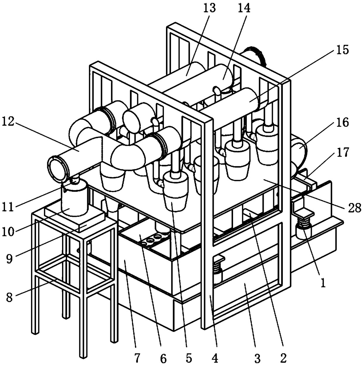
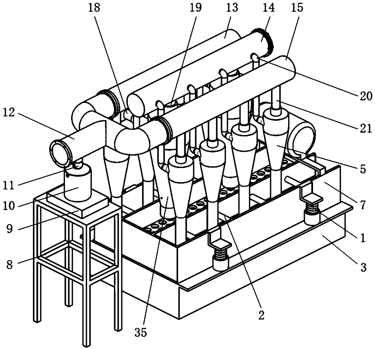
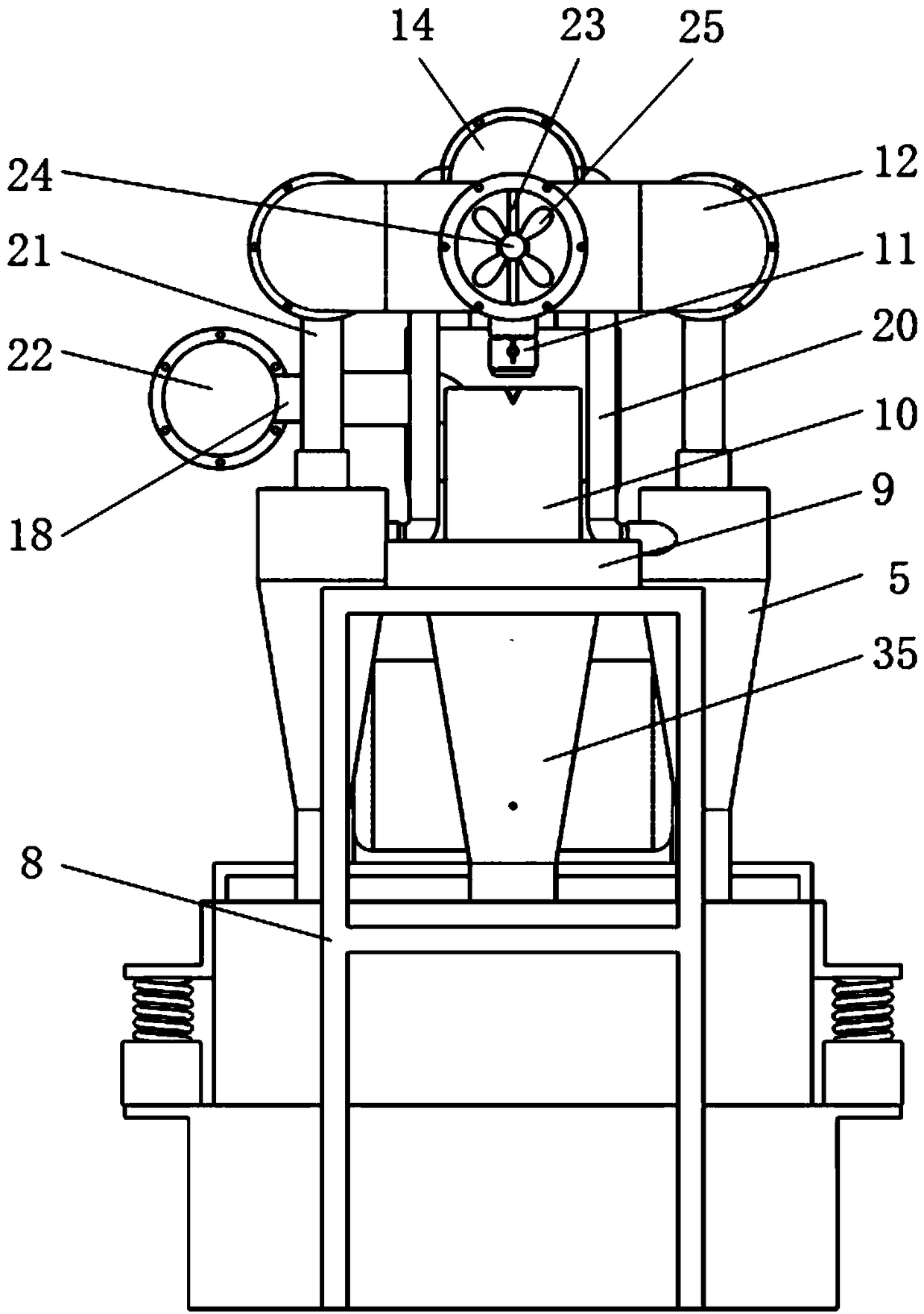
[0034] Such as Figure 1-14 As shown, a mud and sand removal device for drilling fluid of the present invention comprises a fixed support frame 4, a cyclone desilter 5, an electronic scale support 8, an electronic scale 9, a beaker 10, a valve 11, a confluence pipe 12, a third Mud pipe 13, second mud pipe 14, fourth mud pipe 15, desander inlet ...
PUM
Abstract
The invention relates to a mud and sand removal device for drilling fluid, and belongs to the field of petroleum machinery. The mud and sand removal device for the drilling fluid comprises a rotational flow desilter, a beaker, a valve, a collecting pipe, a desander slurry inlet pipe, a desander overflow pipe, a desilter slurry inlet pipe, a slurry inlet pipe overflow pipe, a vertical pipe, a vertical pipe supporting column, a small screen net, a supporting pipe, a rotational flow desander, a vibrating screen, a stirring device and the like. The valve is opened, the drilling fluid in the collecting pipe flows into the beaker through the valve, and the drilling fluid after mud and sand removal is conveniently sampled to conveniently analyze a using effect of the mud and sand removal device for drilling fluid. The structure is compact, the rotational flow desander and the rotational flow desilter are arranged intensively, so that treated drilling fluid waste solid phase is discharged intensively, and the occupied area of the device is saved. The vertical pipe is arranged in the rotational flow desander, the small screen net is arranged at the lower end of the vertical pipe, mud and sand in the drilling fluid is filtered again by the small screen net, and the rotational flow desander effect of the drilling fluid is enhanced. The small screen net can overturn in the vertical pipe toshake off the mud and sand on the small screen net.
Description
technical field [0001] The invention relates to a mud and sand removal device for drilling fluid, which belongs to the field of petroleum machinery. Background technique [0002] The solid particles in the mud drilling fluid are divided into harmful solid phase and useful solid phase. Cuttings are the most important harmful solid phase in the mud drilling fluid, and their density is higher than other components in the drilling fluid. It will affect the physical properties of the drilling fluid, and increase the density, viscosity, dynamic shear force, water loss, mud cake, abrasiveness, viscosity and flow resistance of the drilling fluid. During the drilling process, the cuttings will also damage the oil and gas layers. Reduce the drilling speed, increase the torque of the turntable, and the tripping and tripping encounter resistance, causing sticking and sticking, causing downhole complex situations such as lost circulation and blowout. At the same time, cuttings in the mud...
Claims
Application Information
Patent Timeline
Application Date:The date an application was filed.
Publication Date:The date a patent or application was officially published.
First Publication Date:The earliest publication date of a patent with the same application number.
Issue Date:Publication date of the patent grant document.
PCT Entry Date:The Entry date of PCT National Phase.
Estimated Expiry Date:The statutory expiry date of a patent right according to the Patent Law, and it is the longest term of protection that the patent right can achieve without the termination of the patent right due to other reasons(Term extension factor has been taken into account ).
Invalid Date:Actual expiry date is based on effective date or publication date of legal transaction data of invalid patent.