
Automatic ventilator adopting corridor wind energy

A technology of automatic ventilation and wind energy, which is applied in the direction of machines/engines, liquid fuel engines, and components of pumping devices for elastic fluids, etc., which can solve the problem of increased power consumption, small ventilation flow, and poor practical effects To reduce the possibility of electrical fires, enhance the ventilation effect, and increase economic benefits

Pending Publication Date: 2019-02-15
柳州埃锡科技有限公司
View PDF9 Cites 0 Cited by
  • Summary
  • Abstract
  • Description
  • Claims
  • Application Information

AI Technical Summary

Problems solved by technology

The actual effect of this method of using the air duct formed by the groove and using the flow of natural air to assist the indoor ventilation is very poor
And in most cases, the angle between the wind direction of the corridor wind and the plane where the window wall is located is not large, even 0 (that is, parallel). The angle between the plane and the plane where the window wall is located is close to 0 (approximately parallel). At this time, pushing the window door can not change the air flow into the room; Although the windows and doors can be opened to a certain direction to draw the wind into the room, the purpose cannot be achieved when the wind direction changes, unless the direction of opening the windows and doors is manually changed; therefore, it is not easy for the corridor wind to enter the room automatically from the windows of the current buildings
Since the indoor ventilation flow is not large in the natural state, it is often necessary to turn on the exhaust ventilation fan, but this will increase the power consumption, which is not conducive to energy conservation and environmental protection

Method used


Image

  • Automatic ventilator adopting corridor wind energy
  • Automatic ventilator adopting corridor wind energy
  • Automatic ventilator adopting corridor wind energy

Examples


Embodiment 1

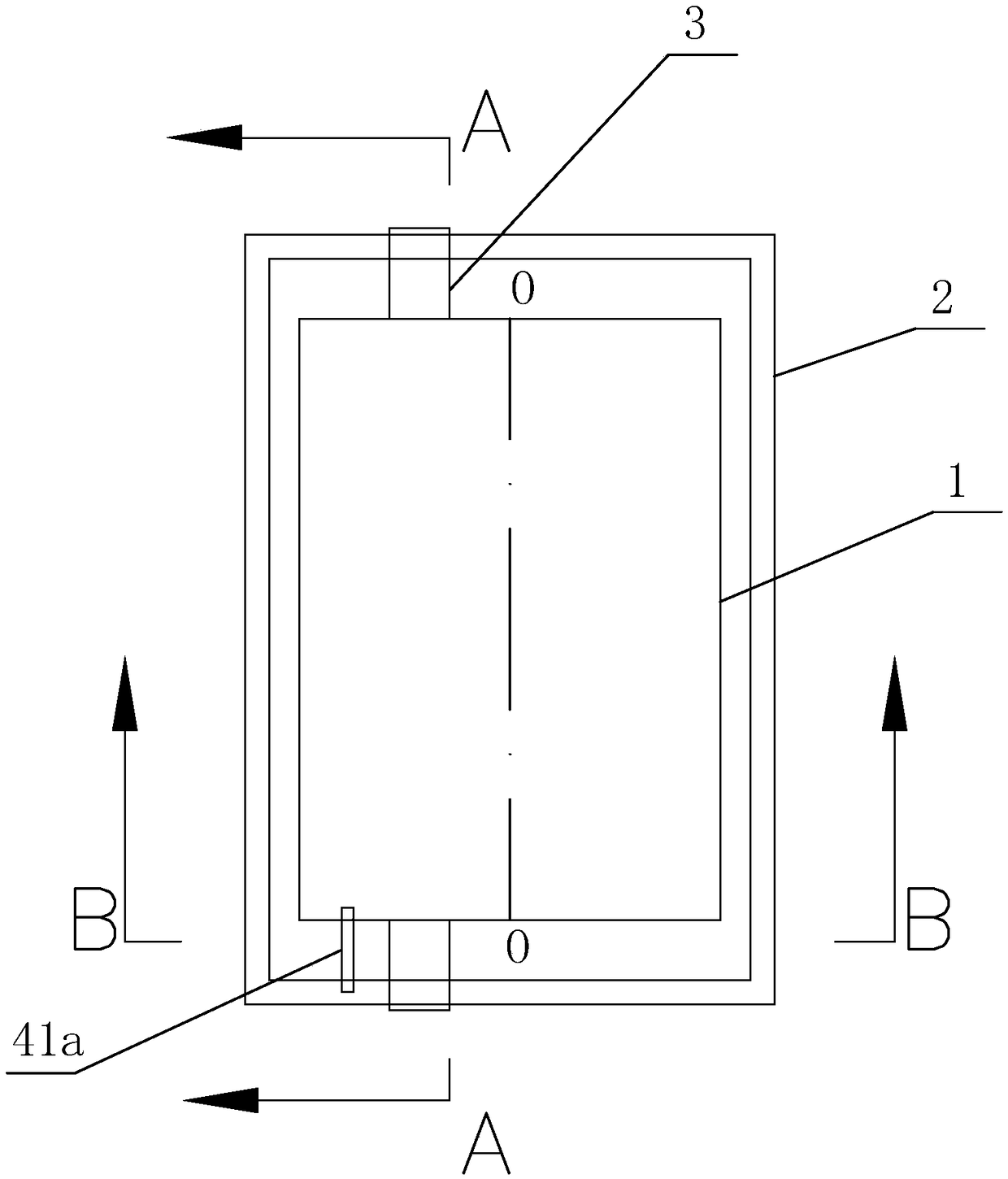
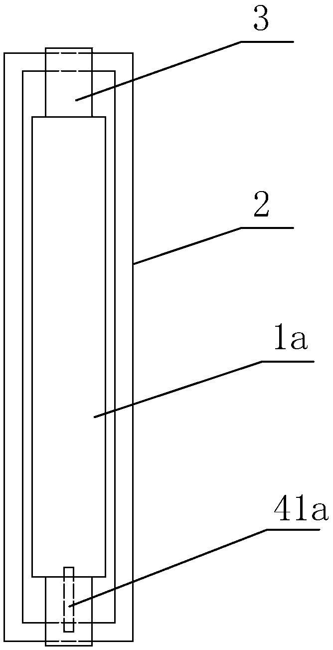
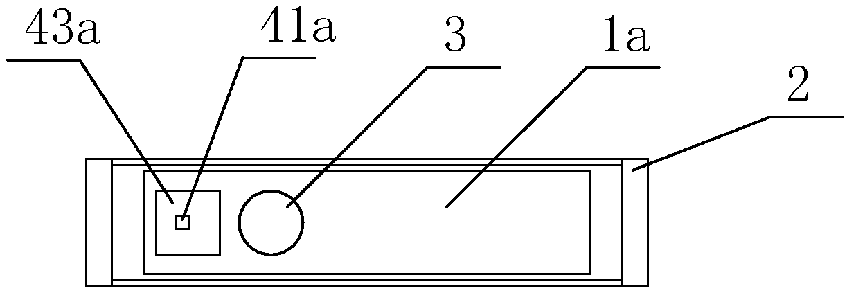
[0052] The basic structure of the gallery wind energy automatic ventilation fan of the present embodiment 1 is as described above, see Figure 1-Figure 2 , including a rectangular fan blade 1a with a certain thickness, a rotating shaft 3, a fan blade outer frame device 2 and a limiting device; the rotating shaft 3 is arranged on one side of the central axis O-O of the fan blade, and the rotating shaft 3 Installed in the fan blade outer frame device 2 , the fan blade 1 is installed in the fan blade outer frame device 2 through the rotating shaft 3 . The limiting device of the present embodiment 1 combines image 3 , Figure 4 , Figure 5 To illustrate, the limiting device includes a sliding rod I41a and a limiting groove I43a; the limiting groove I43a is arranged at the bottom of the fan blade and is located on the left side of the rotating shaft. A chute I42a is opened on the bottom upper surface of the fan blade outer frame device 2 (see Figure 5 ), the chute I42a is loc...

Embodiment 2

[0054] The basic structure of the gallery wind energy automatic ventilation fan of the present embodiment 2 is as described in the embodiment 1, the difference is that the fan blade thickness of the present embodiment 2 is thinner than that of the embodiment 1, and the installation of the limiting device of the present embodiment 2 different ways. It specifically includes a rectangular fan blade 1b, a rotating shaft 3, a fan blade outer frame device and a limiting device; the rotating shaft 3 is arranged on one side of the central axis of the fan blade, and the rotating shaft 3 is installed on the fan blade outer frame In the device, the fan blade is installed in the fan blade outer frame device through the rotating shaft 3 . The limiting device of this embodiment 2 combines Figure 10 To illustrate, the limiting device includes a sliding rod II41b and a limiting groove II43b; the sliding rod II41b is arranged at the bottom of the fan blade through the sliding groove II42b, a...

Embodiment 3

[0057] The corridor wind energy automatic ventilation fan of the present embodiment 3 includes a fan blade, a rotating shaft, a fan blade outer frame device and a limit device that limits the maximum swing angle of the fan blade; one side of the fan blade is installed with a hinge or a hinge 5 ( see Figure 16-Figure 18 ), the hinge or hinge 5 is installed on the side of the fan blade outer frame device as a rotating shaft; the limiting device includes a slider 42c and two screws 41c fixed on the slider 42c; the two screws 41c is arranged on both sides of the fan blade, and the slider 42c is slidably mounted on the outer frame of the fan blade. The limiting device of the third embodiment limits the maximum swing angle of the fan blade by adjusting the relative distance between the slider 42c and the hinge or the hinge 5 so that the fan blade is stuck between the two screws 41C, for example, the slider 42c is close to the hinge Or the maximum included angle when the loose-leaf...


PUM


Abstract

The invention discloses an automatic ventilator adopting corridor wind energy. The automatic ventilator comprises a fan blade, a rotating shaft, a fan blade outer frame device and a limiting device for limiting the maximum swinging angle of the fan blade; the rotating shaft is arranged on one side of the central axis of the fan blade and is mounted inside the fan blade outer frame device; and thefan blade is mounted inside the fan blade outer frame device by the aid of the rotating shaft. By the aid of the automatic ventilator adopting the corridor wind energy, a room can be ventilated efficiently and actively by the aid of the corridor wind energy only, corridor wind can enter the room efficiently regardless of the wind direction, no electric energy or chemical energy is consumed in thewhole process, and all the required energy is the wind energy in the nature.

Description

technical field [0001] The invention relates to the field of building ventilation, in particular to a corridor wind energy automatic ventilating fan for efficiently and actively ventilating a room by utilizing the corridor wind energy. Background technique [0002] Corridor air is a general term for moving air that flows between two buildings or in a corridor. At present, in order to enhance the ventilation effect of the building, its outer contour will not be a flat plane, and a certain groove is often built as an air duct. On the one hand, the Brownian motion of the air in the groove can be used to assist indoor ventilation. On the other hand, the pressure generated by the corridor wind on the air in the groove is used to assist indoor ventilation. The actual effect of this method of assisting indoor air exchange by utilizing the air channel formed by the groove and by means of the flow of natural air is very poor. And in most cases, the angle between the wind direction ...

Claims


Application Information

Patent Timeline
IPC IPC(8): F04D25/04F04D25/08F04D29/00
CPCF04D25/04F04D25/08F04D29/002
Inventor 李海金谢靖雯吴宝深凌玉兰吴宝锟凌细兰杨青勇钟镇隆吴锦斌施小芳吴与伦冯秋华吴志捷张宇琪
Owner 柳州埃锡科技有限公司
Learn More