Ultrasound flowmeter and method for regulating transducers
A technology of ultrasonic flowmeter and flowmeter, which is applied in the direction of measuring flow/mass flow, liquid/fluid solid measurement, instruments, etc., and can solve problems such as signal deviation
- Summary
- Abstract
- Description
- Claims
- Application Information
AI Technical Summary
Problems solved by technology
Method used
Image
Examples
no. 1 example
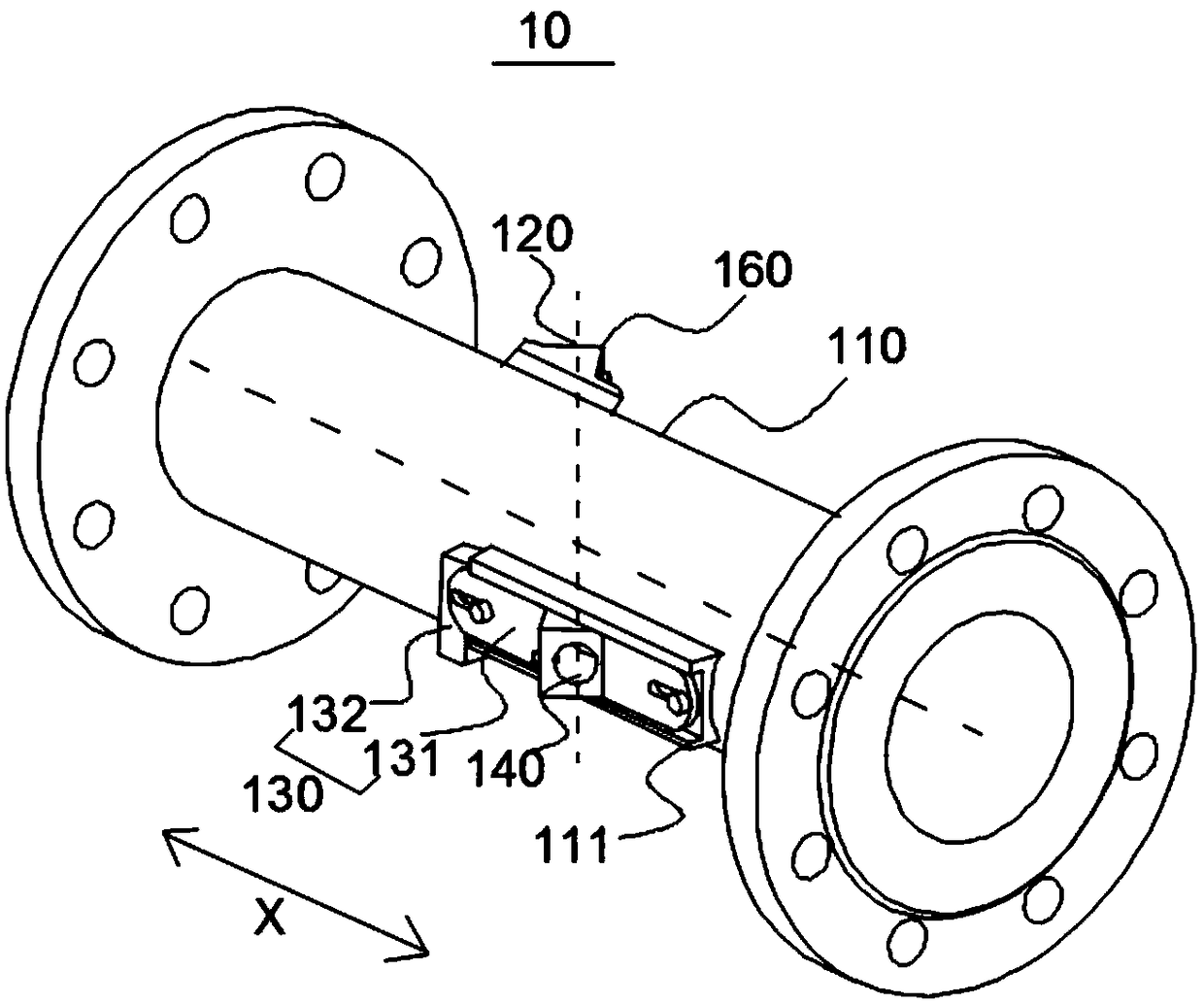
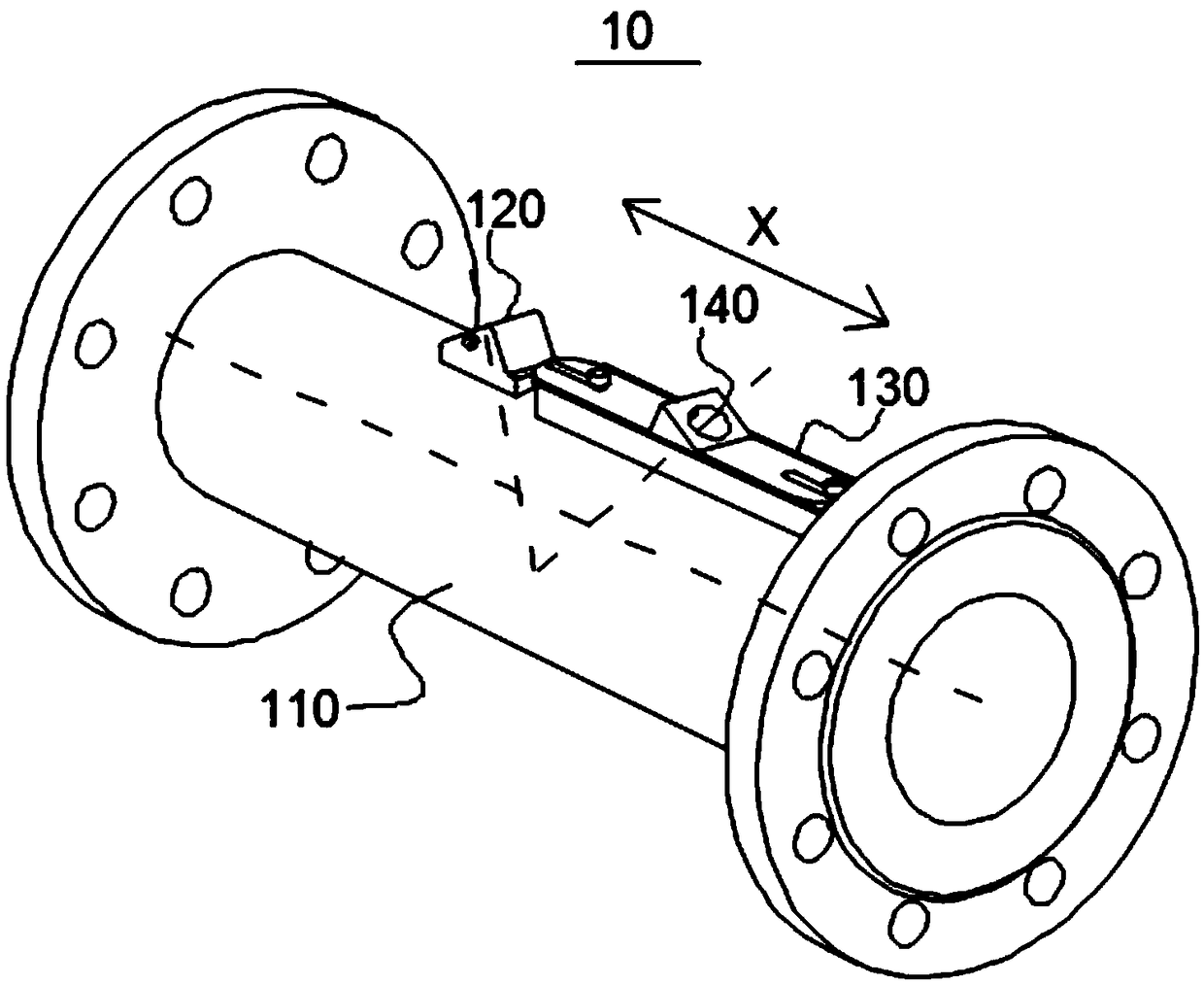
[0070] This embodiment provides an ultrasonic flowmeter 10, please refer to figure 1 or figure 2 , the ultrasonic flowmeter 10 includes a flowmeter housing 110 , an adjustment mechanism 130 , a first transducer 120 , and a second transducer 140 . in, figure 1 Shown is a schematic structural diagram of installing the first transducer 120 and the second transducer 140 in a transmission-type installation manner, figure 2 What is shown is a structural diagram of installing the first transducer 120 and the second transducer 140 in a refraction installation manner.
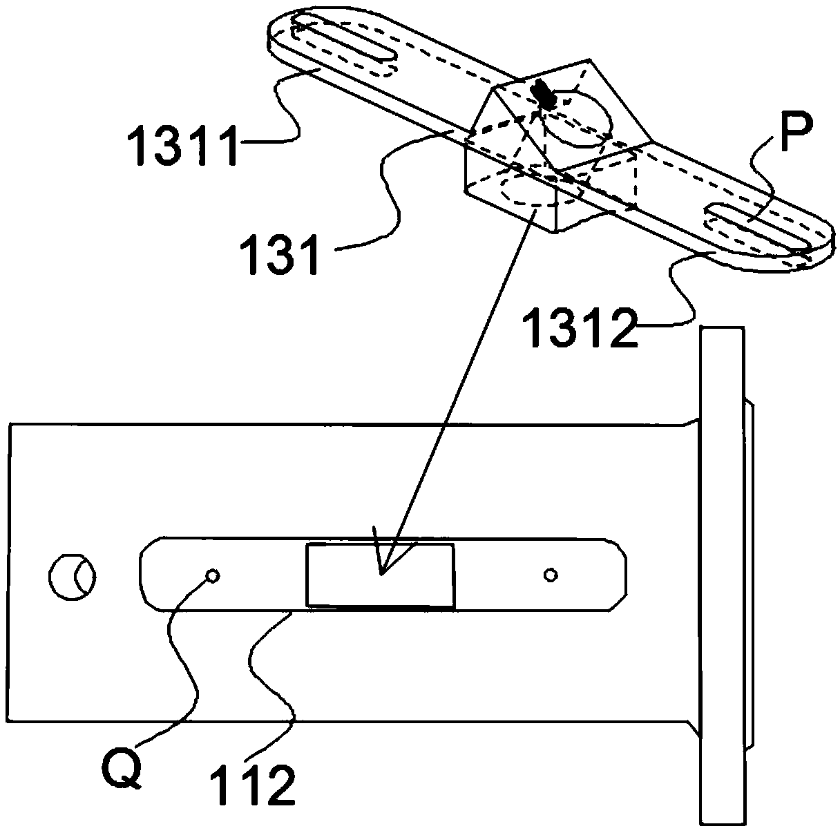
[0071] In this embodiment, the second transducer 140 is installed on the adjustment mechanism 130, and the adjustment mechanism 130 is installed on the flowmeter housing 110, and the adjustment mechanism 130 can drive the second transducer 140 in the first preset direction (see figure 1 , figure 2 in the "X" direction) movement. Wherein, the first preset direction refers to the extension direction of the ultras...
no. 2 example
[0106] This embodiment provides an ultrasonic flowmeter 20, please refer to Image 6 , the ultrasonic flowmeter 20 in this embodiment includes a flowmeter housing 210 and multiple sets of measuring devices 220 . Wherein, any group of measuring devices 220 includes a first transducer, an adjustment mechanism, and a second transducer.
[0107] The first transducer can be directly embedded on the flowmeter housing 210, or can be installed on the flowmeter housing 210 through a fixed base.
[0108] The second transducer is mounted on the adjustment mechanism, which is mounted on the flow meter housing 210 . The second transducer can receive the ultrasonic wave emitted by the first transducer.
[0109] Wherein, the adjustment mechanism can drive the second transducer to move in the first preset direction under the working state. The first preset direction may be the forward flow direction of the medium to be tested, or the reverse flow direction of the medium to be tested.
[0...
no. 3 example
[0113] This embodiment provides a method for adjusting a transducer, which is applied to the ultrasonic flowmeter provided in the foregoing embodiments. The ultrasonic flowmeter includes an adjustment mechanism. If the ultrasonic transducer is installed on the adjustment mechanism, the adjustment mechanism can Drive the ultrasonic transducer to move. For other details of the ultrasonic flowmeter, the adjustment mechanism, the first transducer, and the second transducer mentioned in this embodiment, please refer to the relevant descriptions in the foregoing embodiments, and details will not be repeated here.
[0114] see Figure 7 , the method includes step S310-step S340. The following will combine Figure 8 The described working principle is Figure 7 The method is explained in detail. in, Figure 8 A and B in represent two ultrasonic transducers respectively.
[0115] Step S310: Calculate the instantaneous flow velocity of the medium to be measured.
[0116] The insta...
PUM
 Abstract
Description
Claims
Application Information
 - R&D
- Intellectual Property
- Life Sciences
- Materials
- Tech Scout
- Unparalleled Data Quality
- Higher Quality Content
- 60% Fewer Hallucinations
Browse by: Latest US Patents, China's latest patents, Technical Efficacy Thesaurus, Application Domain, Technology Topic, Popular Technical Reports.
© 2025 PatSnap. All rights reserved.Legal|Privacy policy|Modern Slavery Act Transparency Statement|Sitemap|About US| Contact US: help@patsnap.com


