Microphone detection method and system, and microphone

A detection method and detection system technology are applied in the detection of microphones and the field of microphones, which can solve the problems of inability to locate and locate the microphone chip.

Inactive Publication Date: 2019-02-15
AMOLOGIC (SHANGHAI) CO LTD
View PDF5 Cites 5 Cited by
  • Summary
  • Abstract
  • Description
  • Claims
  • Application Information

AI Technical Summary

Problems solved by technology

[0003] Aiming at the problem of being unable to troubleshoot and locate microphone chip failures, a method, system and microphone for detecting microphones that can troubleshoot and locate faulty microphone chips are now provided.

Method used


Image

  • Microphone detection method and system, and microphone
  • Microphone detection method and system, and microphone
  • Microphone detection method and system, and microphone

Examples


Embodiment Construction

[0045] The following will clearly and completely describe the technical solutions in the embodiments of the present invention with reference to the accompanying drawings in the embodiments of the present invention. Obviously, the described embodiments are only some, not all, embodiments of the present invention. Based on the embodiments of the present invention, all other embodiments obtained by persons of ordinary skill in the art without creative efforts fall within the protection scope of the present invention.

[0046] It should be noted that, in the case of no conflict, the embodiments of the present invention and the features in the embodiments can be combined with each other.

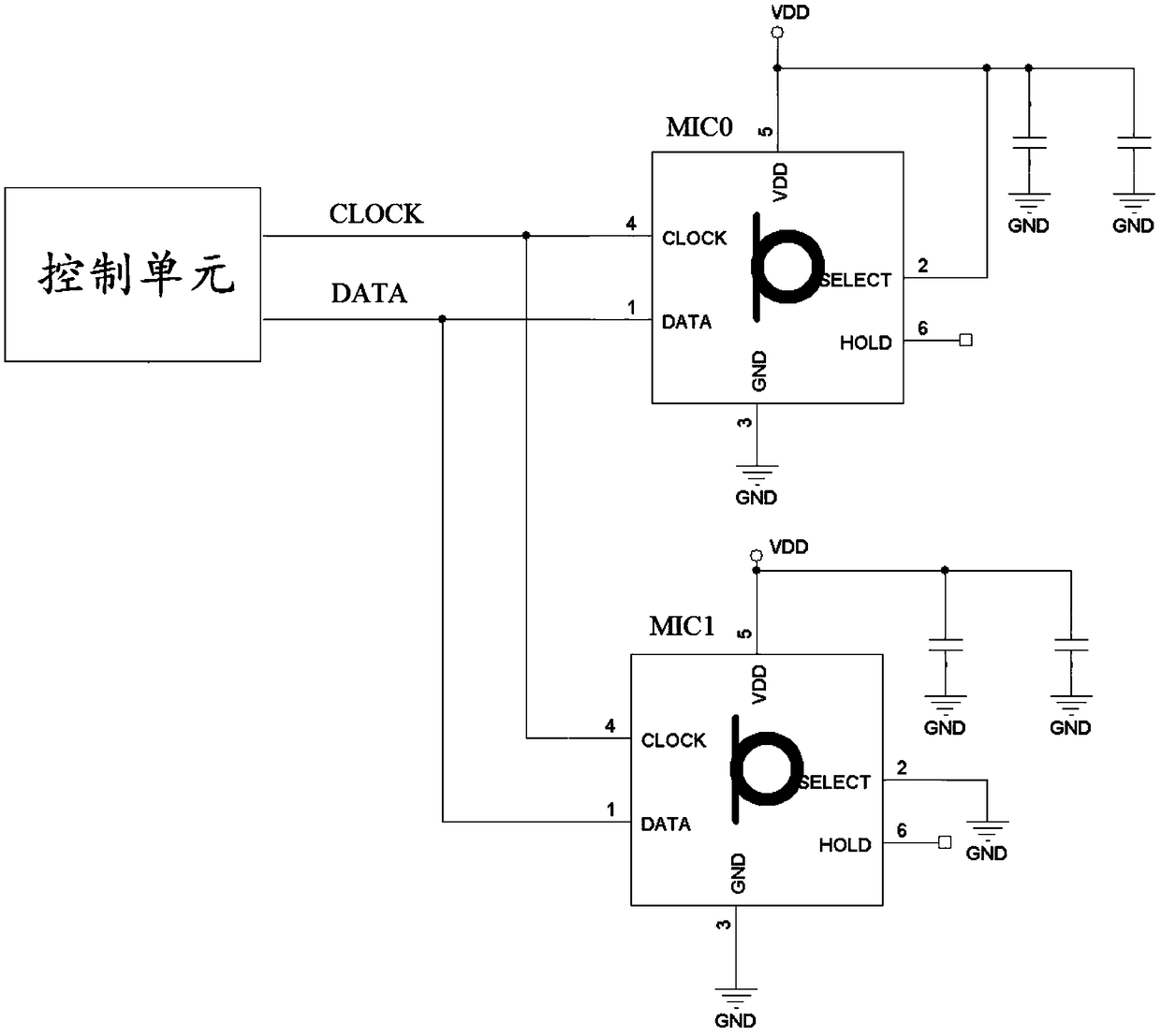
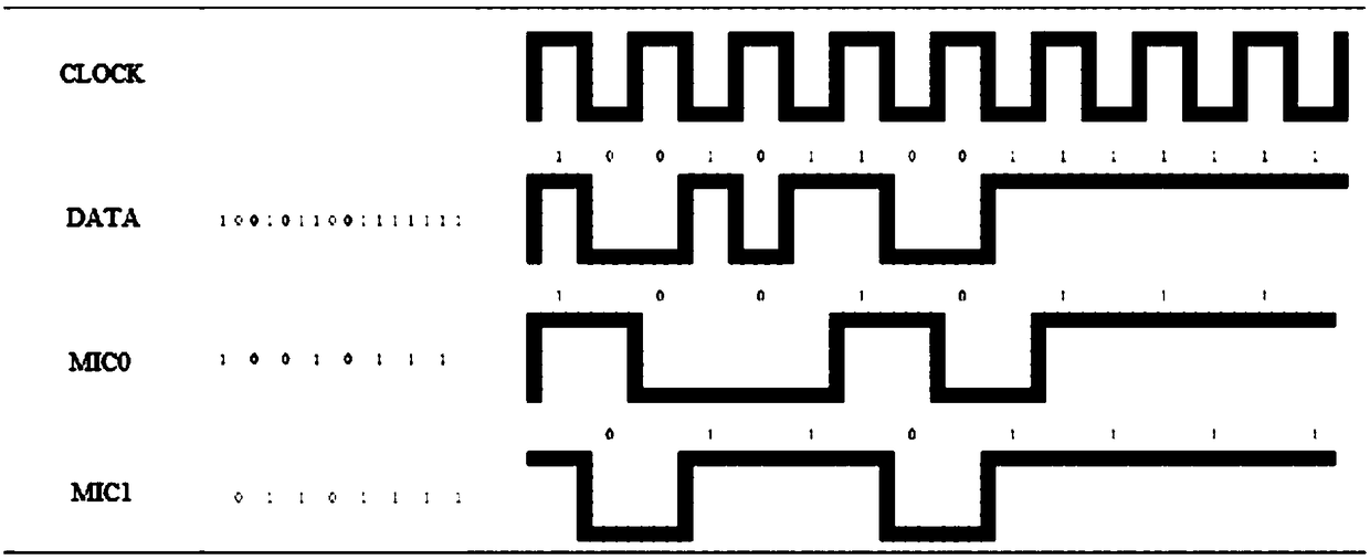
[0047] For a microphone device with multiple pairs of microphone chips, a pair of microphone chips is taken as an example for the following description: When both microphone chips (MIC0 and MIC1) are in normal working state, refer to Figure 1-Figure 2 Shown:

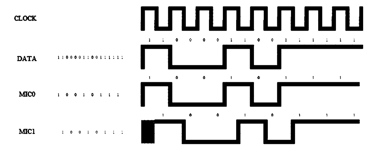
[0048] The data of DATA is normal:...


PUM


Abstract

The invention discloses a microphone detection method and system, and a microphone, and belongs to the technical field of the audio. The microphone detection method is applied to a microphone, and themicrophone comprises at least one pair of audio receiving units; the detection method comprises the following steps: adjusting trigger levels of at least one pair of audio receiving units; acquiringdigital signals output by at least one pair of audio receiving units; and analyzing the digital signals to acquire working states of at least one pair of audio receiving units. By adjusting the trigger levels of at least one pair of audio receiving units, the audio receiving units can send the data signal along a rising edge or a descending edge of a clock signal, the digital signals output by atleast one pair of audio receiving units are analyzed to acquire the working states of at least one pair of audio receiving units, thereby realizing an aim of troubleshooting and positioning the audioreceiving units in fault.

Description

technical field [0001] The invention relates to the field of audio technology, in particular to a microphone detection method, system and microphone. Background technique [0002] Based on PDM (pulse code modulation, pulse density modulation) signal characteristics (reference figure 1 ), one DATA interface of the control unit can be connected to two microphone chips (MIC0 and MIC1). Since the DATA pin of the microphone has parasitic capacitance, if the interface of one PDM interface chip is weakly welded or damaged, another good PDM interface chip will be It will maintain the same signal as before in the high configuration (HighZ) state, resulting in the same data of the two PDM interface chips (MIC0 and MIC1). At present, it is difficult to troubleshoot and locate the faulty microphone chip if there are multiple microphone chips with weak soldering, which will affect voice recognition and user experience. Contents of the invention [0003] Aiming at the problem that the...

Claims


Application Information

Patent Timeline
Patent Type & Authority Applications(China)
IPC IPC(8): H04R29/00
CPCH04R29/004
Inventor 张坤
Owner AMOLOGIC (SHANGHAI) CO LTD
Why Eureka
Try Eureka