
Rotary exhaust gas purification treatment device

A waste gas purification and treatment device technology, which is applied to chemical instruments and methods, dispersed particle separation, dispersed particle filtration, etc., can solve the problems of human health hazards, short contact time, and degradation of atmospheric environment quality, so as to improve the contact area and exposure time, increasing the effect of uniformity

Inactive Publication Date: 2019-02-19
南京安伦化工科技有限公司
View PDF8 Cites 0 Cited by
  • Summary
  • Abstract
  • Description
  • Claims
  • Application Information

AI Technical Summary

Problems solved by technology

[0002] In the process of human production and life, a large amount of waste gas will be produced, especially in chemical plants, steel plants, and pharmaceutical factories. The industrial waste gas emitted by various production enterprises is the main source of air pollution. At present, many of the waste gases emitted by many factories contain Acidic gas substances, if these acidic waste gases are discharged directly into the atmosphere without treatment and meet the standards, it will inevitably lead to a decline in the quality of the atmospheric environment and bring harm to human health. During liquid neutralization treatment, the contact time is short, and the neutralization reaction is insufficient, especially when the discharge rate of acid gas is large or the discharge rate is fast, resulting in incomplete purification

Method used


Image

  • Rotary exhaust gas purification treatment device
  • Rotary exhaust gas purification treatment device
  • Rotary exhaust gas purification treatment device

Examples


Embodiment Construction

[0013] The present invention will be further explained below in conjunction with the accompanying drawings and specific embodiments. It should be understood that the following specific embodiments are only used to illustrate the present invention and are not intended to limit the scope of the present invention. It should be noted that the words "front", "rear", "left", "right", "upper" and "lower" used in the following description refer to the directions in the drawings, and the words "inner" and "outer ” refer to directions towards or away from the geometric center of a particular part, respectively.

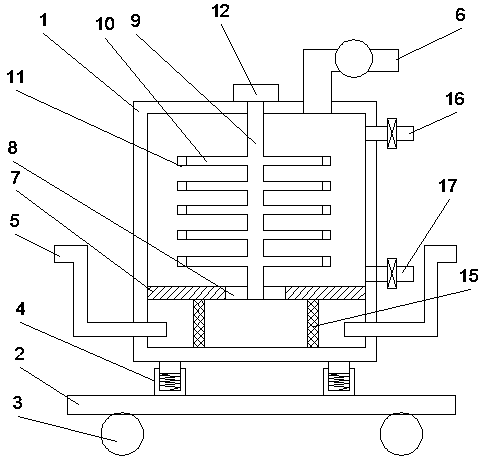
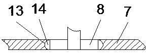
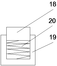
[0014] Such as figure 1 and figure 2 A rotary exhaust gas purification treatment device is shown, which includes a box body 1 and a moving plate 2, and is characterized in that: the lower surface of the moving plate 2 is connected with a pulley 3, and the upper surface is provided with a support base 4, and the box body 1 Set on the support base 4, the two sides of the box b...


PUM


Abstract

The invention discloses a rotary exhaust gas purification treatment device. The rotary exhaust gas purification treatment device comprises a box body and a moving plate, wherein the lower surface of the moving plate is connected with pulleys, the upper surface of the moving plate is provided with a supporting base, the box body is arranged on the supporting base, the two sides of the box body areprovided with air inlet pipelines, the top of the box body is provided with an air outlet pipeline, the box body is internally provided with a horizontal partition plate, the partition plate is internally provided with a rotating disc, the box body is internally provided with a hollow stirring shaft of which the bottom is provided with an opening, the stirring shaft is provided with a stirring pipe communicated with the stirring shaft, the end of the stirring pipe is provided with a one-way valve, the top of the stirring shaft is connected with a driving motor outside the box body, the bottomof the stirring shaft penetrates through the rotating disc and extends to the bottom of the rotating disc, a sliding groove is arranged at the intersecting position of the rotating disc and the partition plate, and the sliding groove is internally provided with a seal ring. The rotary exhaust gas purification treatment device has the advantages that the contact area and contact time during neutralization reaction between acidic exhaust gas and an alkaline liquid can be increased, and the efficiency of the neutralization reaction is improved.

Description

technical field [0001] The invention relates to the technical field of waste gas treatment, in particular to a rotary waste gas purification treatment device. Background technique [0002] In the process of human production and life, a large amount of waste gas will be produced, especially in chemical plants, steel plants, and pharmaceutical factories. The industrial waste gas emitted by various production enterprises is the main source of air pollution. At present, many of the waste gases emitted by many factories contain Acidic gas substances, if these acidic waste gases are discharged directly into the atmosphere without treatment and meet the standards, it will inevitably lead to a decline in the quality of the atmospheric environment and bring harm to human health. During liquid neutralization treatment, the contact time is short, and the neutralization reaction is not sufficient, especially when the discharge rate of acid gas is large or the discharge rate is fast, res...

Claims


Application Information

Patent Timeline
IPC IPC(8): B01D53/40B01D53/78B01D46/12
CPCB01D46/12B01D53/40B01D53/78
Inventor 陈桂平相解
Owner 南京安伦化工科技有限公司
Learn More