
A positioning mechanism for an automatic shrinking machine

A technology of positioning mechanism and tube shrinking machine, which is applied in positioning devices, feeding devices, manufacturing tools, etc., can solve the problems of poor positioning effect and inability to effectively improve the quality of shrinking tubes, etc., to achieve convenient operation, prevent damage to the outer wall of the pipeline, The effect of improving the efficiency of tube shrinkage

Active Publication Date: 2020-11-17
济南市唯振信息科技有限公司
View PDF15 Cites 0 Cited by
  • Summary
  • Abstract
  • Description
  • Claims
  • Application Information

AI Technical Summary

Problems solved by technology

[0002] The function of the automatic shrinking machine is to process various styles on one end or both ends of the pipe, and the pipe needs to be fixed during the processing to prevent deviations during the processing and cause unnecessary losses. The traditional fixing device generally It uses a guide tube to insert one end of the pipe into the telescopic device for processing. The positioning effect is poor and the quality of the shrink tube cannot be effectively improved.

Method used


Image

  • A positioning mechanism for an automatic shrinking machine
  • A positioning mechanism for an automatic shrinking machine
  • A positioning mechanism for an automatic shrinking machine

Examples


Embodiment Construction

[0020] The following will clearly and completely describe the technical solutions in the embodiments of the present invention with reference to the accompanying drawings in the embodiments of the present invention. Obviously, the described embodiments are only some, not all, embodiments of the present invention. Based on the embodiments of the present invention, all other embodiments obtained by persons of ordinary skill in the art without making creative efforts belong to the protection scope of the present invention.

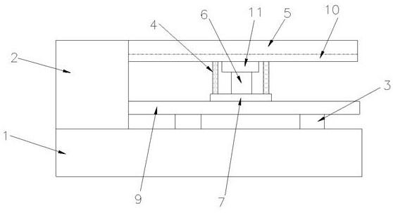
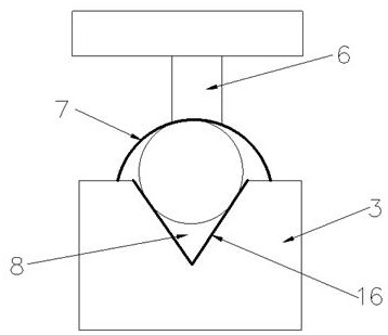
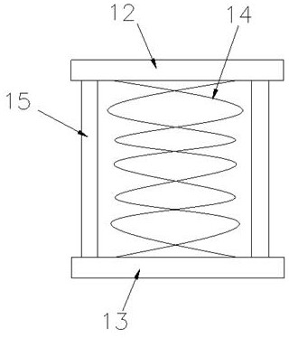
[0021] see Figure 1-3 , the present invention provides a technical solution: a positioning mechanism for an automatic tube shrinking machine, including a base 1 and a tube shrinking machine body 2, the tube shrinking machine body 2 is installed on the upper side of the base 1, and the base 1 is also provided with There is a pipe fixing assembly, the pipe fixing assembly includes a support base 3, a buffer assembly 4, an upper beam 5, a telescoping mechanism 6...


PUM

PropertyMeasurementUnit
lengthaaaaaaaaaa
thicknessaaaaaaaaaa

Abstract

The invention discloses a positioning mechanism of an automatic pipe contracting machine. The positioning mechanism of the automatic pipe contracting machine comprises a base and a pipe contracting machine body; the pipe contracting machine body is mounted on one side of the upper end of the bas; a pipe fixing module is arranged on the base; the pipe fixing module comprises a support base, a buffer module, an upper cross beam, an extension mechanism and a support block; a V-shaped clamping groove is formed in the upper end surface of the support base; a pipe to be contracted is clamped in theV-shaped clamping groove; the upper cross beam is mounted right above the pipe fixing module; a transverse slide rail is arranged at the lower end of the upper cross beam, and is slidingly connected with a slide block; the extension mechanism is mounted at the lower end of the slide block; a support block is mounted at the lower end of the extension mechanism, and is of an arc structure; and a buffer module is mounted between the upper end surface of the support block and the lower end surface of the upper cross beam. The positioning mechanism of the automatic pipe contracting machine is novelin structural design and convenient to operate, can realize quick fixing and positioning of pipes, improves the pipe contracting efficiency, and in addition, achieves an excellent buffering effect toprevent damage of the outer walls of the pipes.

Description

technical field [0001] The invention relates to the technical field of tube shrinking machines, in particular to an automatic tube shrinking machine positioning mechanism. Background technique [0002] The function of the automatic shrinking machine is to process various styles on one end or both ends of the pipe, and the pipe needs to be fixed during the processing to prevent deviations during the processing and cause unnecessary losses. The traditional fixing device generally It adopts a guide tube, and one end of the pipe is inserted into the telescopic device through the guide tube for processing. The positioning effect is poor, and the quality of the shrink tube cannot be effectively improved. Contents of the invention [0003] The purpose of the present invention is to provide a positioning mechanism for an automatic tube shrinking machine to solve the problems raised in the above-mentioned background technology. [0004] In order to achieve the above purpose, the p...

Claims


Application Information

Patent Timeline
Patent Type & Authority Patents(China)
IPC IPC(8): B21D41/04B21D43/00
CPCB21D41/04B21D43/00
Inventor 陶建惠潘富山
Owner 济南市唯振信息科技有限公司
Learn More