Battery shock resistance detection device

A detection device and shock resistance technology, applied in the field of battery shock resistance detection devices, can solve the problems of inability to accurately obtain test data, difficult to control the amplitude of spring swing, wrong test data, etc., and to change the test vibration amplitude and Test time, improve work efficiency, compact structure

Active Publication Date: 2022-05-20
江西京九电源科技有限公司 +1
View PDF16 Cites 0 Cited by
  • Summary
  • Abstract
  • Description
  • Claims
  • Application Information

AI Technical Summary

Problems solved by technology

[0002] Batteries are currently used on various tools, and various tools will encounter various environments during use, such as bumping up and down, shaking left and right, vibrations generated by the internal drive assembly, etc. The anti-seismic performance is very important, especially the anti-seismic performance of the entire battery, as well as the internal performance. Although there is a special test device for the anti-seismic performance of the battery in production, the equipment cannot accurately obtain the test data.
[0003] CN107132016A discloses a device for testing the vibration resistance performance of a storage battery. The device only uses a simple cam drive method to drive the storage battery to move up and down. The vibration brought by it is difficult to simulate the actual working environment of the storage battery, making the test data inaccurate
[0004] CN108106803A discloses a vibration test device for solid-state storage batteries. The structure adopted by the device is to push the oil cylinder to cooperate with the drive oil cylinder to drive the battery storage box to shake, and the vibration spring is connected between them. It is difficult to control the amplitude of the spring swing during detection, so that the test data error

Method used


Image

  • Battery shock resistance detection device
  • Battery shock resistance detection device
  • Battery shock resistance detection device

Examples


Embodiment Construction

[0036] The following will clearly and completely describe the technical solutions in the embodiments of the present invention with reference to the drawings in the embodiments of the present invention.

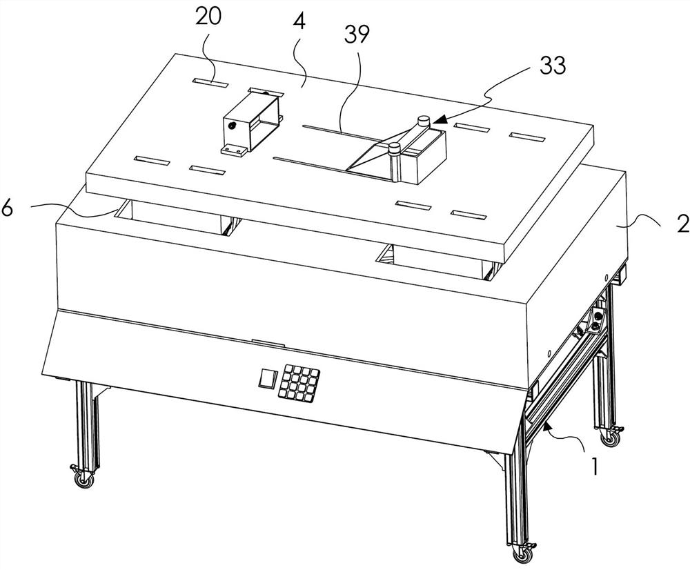
[0037] Such as Figure 1 to Figure 11 As shown, the battery shock resistance testing device of the present invention includes a workbench 1 , an outer cover 2 , a transmission mechanism 3 and a support plate 4 . There is a control panel on the workbench 1, and the control panel is used to control the entire detection device. The working plate 5 arranged on the workbench 1 is fixed on the workbench 1 and separates the upper and lower layers of the workbench 1 so that the motor is at the lower end. Outer cover 2 is installed on the working board 5, and outer cover 2 is used for protecting the internal mechanism, avoids being exposed outside and causing injury to the staff. There is a through hole 6 on the outer cover 2, and the through hole 6 communicates the outside with the ...


PUM


Abstract

The invention discloses a battery shock resistance detection device, which comprises a workbench, an outer cover, a transmission mechanism and a support plate. The support plate is installed on the transmission mechanism. The transmission mechanism is composed of a first motor and a symmetrical rotating shaft. It is set on the work plate on the workbench. The work plate has a first gear and a buffer assembly. The buffer assembly includes a mounting seat, a fixing seat, Limits and tops. The shock resistance testing device of the storage battery is ingenious in design and compact in structure, can change the test vibration amplitude and test time, and can quickly fix and position the storage battery through the fixing component. Then the transmission mechanism is used to simulate the state of the battery in different working environments. At the same time, the ejection mechanism can be used to simulate a relatively strong vibration, which makes the environment of the battery more realistic and has a great influence on the accurate data of the test. help, while improving work efficiency.

Description

technical field [0001] The invention relates to the anti-seismic detection technology, in particular to an anti-seismic detection device of a storage battery. Background technique [0002] Batteries are currently used on various tools, and various tools will encounter various environments during use, such as bumping up and down, shaking left and right, vibrations generated by the internal drive assembly, etc. The anti-seismic performance is very important, especially the anti-seismic performance of the entire battery, as well as the internal performance. Although there is a special test device for the anti-seismic performance of the battery in production, the equipment cannot accurately obtain test data. [0003] CN107132016A discloses a device for testing the vibration resistance performance of a storage battery. The device only uses a simple cam drive method to drive the storage battery to move up and down. The vibration brought by it is difficult to simulate the actual wo...

Claims


Application Information

Patent Timeline
Patent Type & Authority Patents(China)
IPC IPC(8): G01M7/02
CPCG01M7/022Y02E60/10
Inventor 吴明耀郭小群刘三元谢正望
Owner 江西京九电源科技有限公司
Why Eureka
Try Eureka