

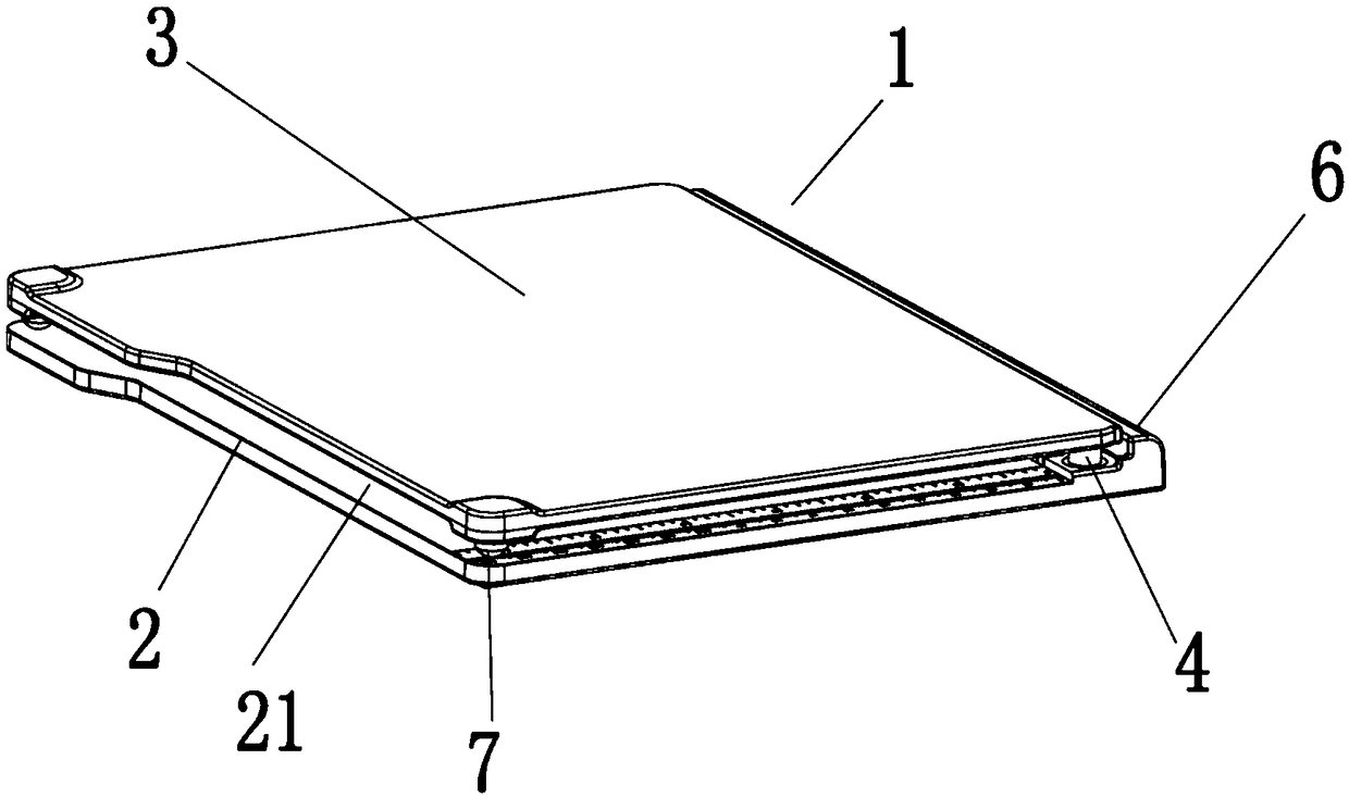
Seal marking machine
A technology of stamping machine and seal, applied in printing, stamping and other directions, can solve the problems of uneven pressing force, difficulty in stamping arrangement position, and imperfect stamping effect, so as to achieve complete and uniform pattern and uniform force on stamps. , the effect of low manufacturing cost
- Summary
- Abstract
- Description
- Claims
- Application Information
AI Technical Summary
Problems solved by technology
Method used
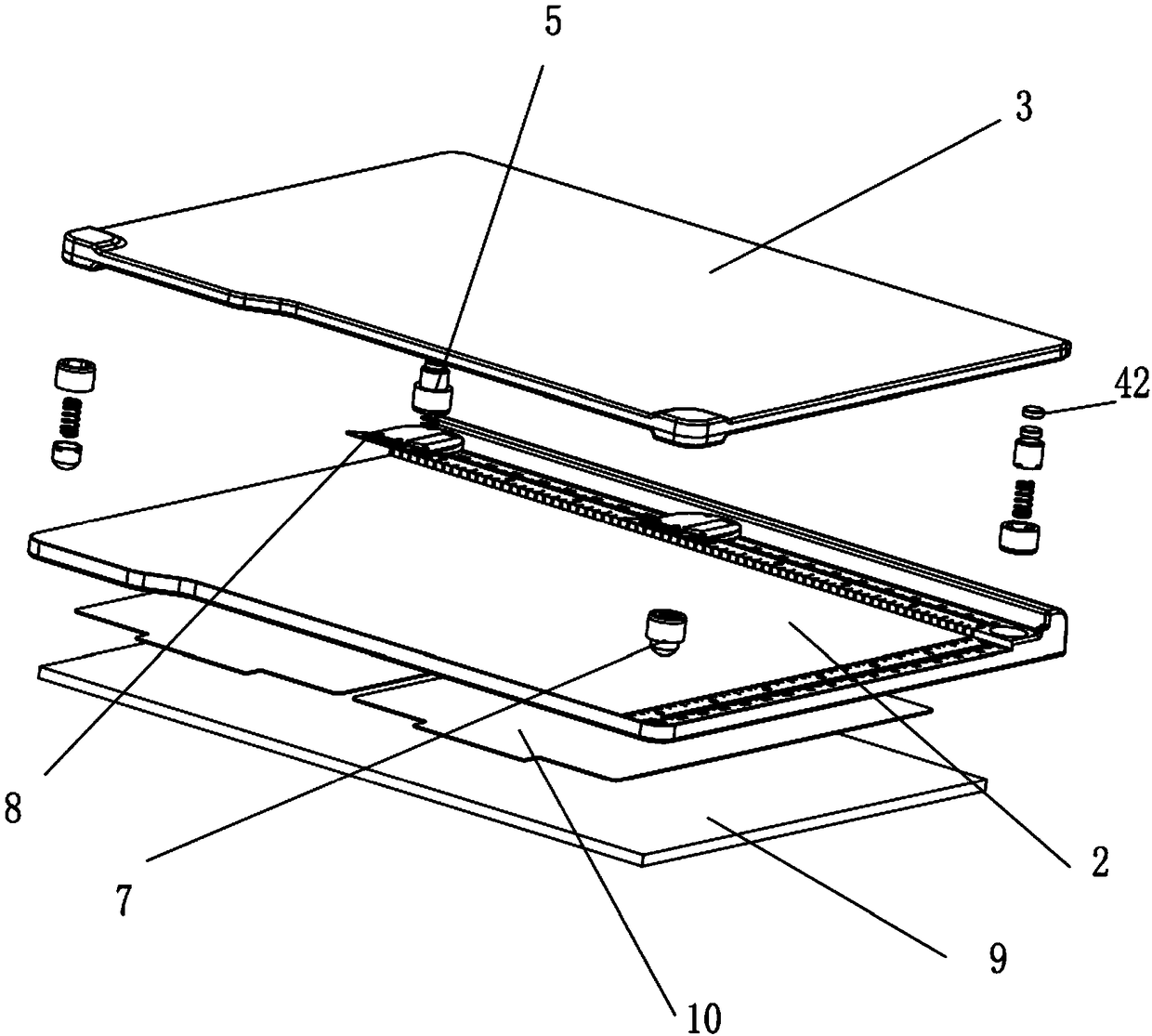
Image

Examples
Embodiment 2
[0057] The structure of this embodiment is basically the same as that of Embodiment 1, the only difference being that the first suction member 41 and the second suction member 42 are both fixedly arranged on the pressure plate 3 or the bottom plate 2 . For example, the first suction part 41 is fixedly arranged on the bottom plate 2, and the second suction part 42 is fixedly arranged on the pressure plate 3.
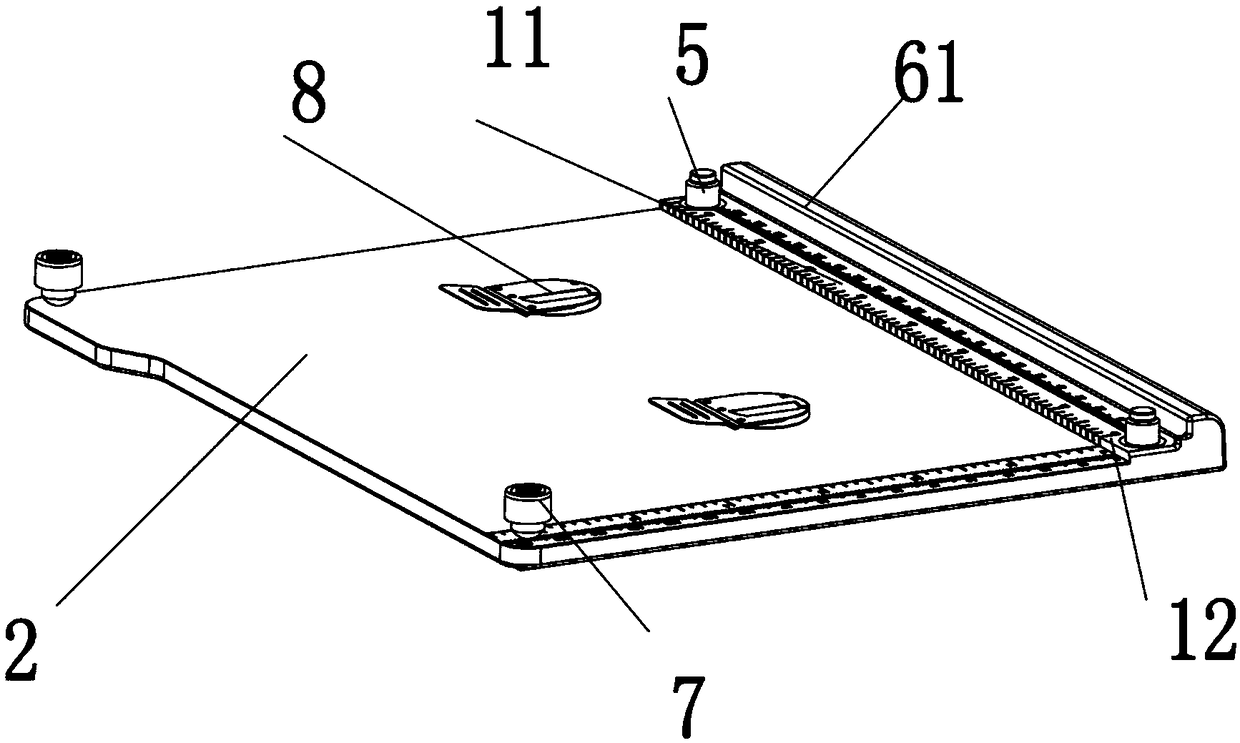
[0058] When this embodiment 2 is in use, the pressing plate 3 is turned up, so that the pressing plate 3 is placed on the bottom plate 2 in a vertical state through the limit block 61 or placed on one side of the bottom plate 2, and then the carrier is placed In the working space 21 on the bottom plate 2, the edge of the carrier is pressed against the side wall of the longitudinal boss 12, the magnet is placed on the carrier, the carrier is fixed, and the stamp is placed on a suitable position on the carrier with reference to the scale mark 11; Rotate the pressing plate 3...
Embodiment 3
[0060] like Figure 10 As shown, in this embodiment 3, a first suction member 41 is fixedly arranged on the bottom plate 2, and a positioning frame 13 is movably connected with the pressure plate 3, and the positioning frame 13 limits the lateral movement of the pressure plate 3 in the positioning frame 13. , the second suction piece 42 is fixedly arranged on the positioning frame 13, and the positioning frame 13 is fixed and suctioned on the bottom plate 2 through the mutual cooperation between the second suction piece 42 and the first suction piece 41, and the pressure plate 3 The elastic telescopic structure 7 embedded in the positioning frame 13 is provided on the side.
[0061] When in use, the carrier is first placed in the working space 21 on the bottom plate 2, the edge of the carrier is pressed against the side wall of the longitudinal boss 12, the magnet is placed on the carrier, the carrier is fixed, and the seal is placed with reference to the scale mark 11. at a ...
PUM
 Abstract
Description
Claims
Application Information