Real-time monitoring method for rainfall inspection in drought and flood areas

A technology for regional inspection and real-time monitoring, applied to rainfall/precipitation gauges, measuring devices, meteorology, etc., can solve the problems of inability to monitor rainfall in real time and the degree of flooding, and achieve good real-time performance, reasonable design, and easy operation simple effect

Pending Publication Date: 2019-02-19
FARMLAND IRRIGATION RES INST CHINESE ACAD OF AGRI SCI
View PDF3 Cites 3 Cited by
  • Summary
  • Abstract
  • Description
  • Claims
  • Application Information

AI Technical Summary

Problems solved by technology

[0002] In recent years, urban waterlogging has occurred from time to time, and some cities are even flooded every time it rains. Urban waterlogging refers to the phenomenon of water accumulation on the ground in the city due to heavy or continuous rainfall exceeding the urban drainage capacity. Once waterlogging occurs, it will inevitably Bringing unpredictable major losses. Flood disasters mainly come from the increase in rainfall and untimely protection. In the existing technology, when the rainfall increases, people cannot detect the degree of flooding and cannot monitor the rainfall in real time.

Method used


Image

  • Real-time monitoring method for rainfall inspection in drought and flood areas

Examples


Embodiment 1

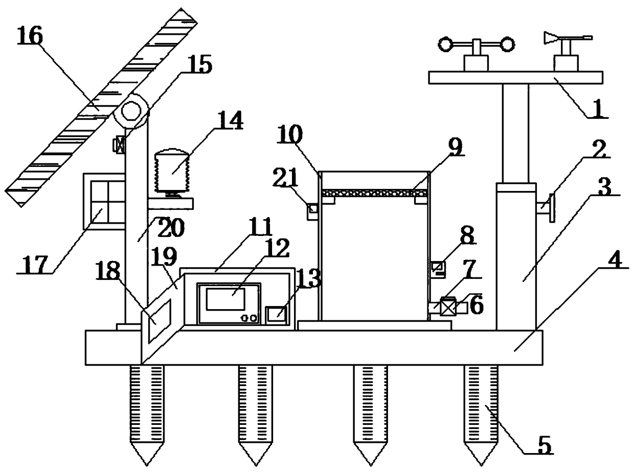
[0025] Such as figure 1 As shown, a method for real-time monitoring of rainfall for inspection of drought and flood areas includes a base plate 4, a solar panel 16, an energy storage inverter power supply 17, a rain gauge 10, and ground piles 5, and a support rod is welded on one side of the top of the base plate 4. 20. The top of the support rod 20 is installed with a solar panel 16 through a rotating shaft, and the bottom of the solar panel 16 is installed with a solar controller 15 through a waterproof cover, and the solar controller 15 is electrically connected to the solar panel 16. The support rod 20 An energy storage inverter power supply 17 is installed through a waterproof box on one side, and the energy storage inverter power supply 17 is electrically connected to the solar controller 15. The other side of the support rod 20 is installed with an air temperature and humidity meter 14 through a horizontal frame. The lifting sleeve 3 is welded on the other side of the t...

Embodiment 2

[0041] Such as figure 1 As shown, a method for real-time monitoring of rainfall for inspection of drought and flood areas includes a base plate 4, a solar panel 16, an energy storage inverter power supply 17, a rain gauge 10, and ground piles 5, and a support rod is welded on one side of the top of the base plate 4. 20. The top of the support rod 20 is installed with a solar panel 16 through a rotating shaft, and the bottom of the solar panel 16 is installed with a solar controller 15 through a waterproof cover, and the solar controller 15 is electrically connected to the solar panel 16. The support rod 20 An energy storage inverter power supply 17 is installed through a waterproof box on one side, and the energy storage inverter power supply 17 is electrically connected to the solar controller 15. The other side of the support rod 20 is installed with an air temperature and humidity meter 14 through a horizontal frame. The lifting sleeve 3 is welded on the other side of the t...


PUM


Abstract

The invention discloses a real-time monitoring device for rainfall inspection in drought and flood areas, comprising a bottom plate, a solar panel, an energy storaging inverter power, a rain gauging cylinder, and ground piles. The top side of the bottom plate is welded with a supporting rod, and the top end of the supporting rod is mounted with the solar panel through a rotating shaft. The bottomof the solar panel is mounted with a solar controller through a waterproof cover, and the solar controller is electrically connected to the solar panel. One side of the supporting rod is mounted withthe energy storaging inverter power through a waterproof box, and the energy storaging inverter power is electrically connected to the solar controller. The other side of the supporting rod is mountedwith an air temperature and humidity meter through a cross frame, and the other side of the bottom plate is welded with a lifting sleeve. The lifting end of the top of the lifting sleeve is connectedto a wind speed and direction meter, and one side of the lifting sleeve is mounted with a rain gauging cylinder through a mounting plate. The real-time monitoring device for rainfall inspection in drought and flood areas is reasonable in design, simple in structure, good in real-time performance, can query monitoring data in various ways, which are suitable for wide-scale promotion.

Description

technical field [0001] The invention belongs to the technical field of rainfall monitoring, and in particular relates to a method for real-time monitoring of rainfall for inspection in drought-flooded areas. Background technique [0002] In recent years, urban waterlogging has occurred from time to time, and some cities are even flooded every time it rains. Urban waterlogging refers to the phenomenon of water accumulation on the ground in the city due to heavy or continuous rainfall exceeding the urban drainage capacity. Once waterlogging occurs, it will inevitably Unpredictable major losses are caused. Flood disasters mainly come from the increase in rainfall and untimely protection. In the existing technology, when the rainfall increases, people cannot detect the degree of flooding and cannot monitor the rainfall in real time. Contents of the invention [0003] The purpose of the present invention is to provide a method for real-time monitoring of rainfall in drought-flo...

Claims


Application Information

Patent Timeline
Patent Type & Authority Applications(China)
IPC IPC(8): G01W1/14
CPCG01W1/14Y02A90/10
Inventor 郭冬冬温新
Owner FARMLAND IRRIGATION RES INST CHINESE ACAD OF AGRI SCI
Why Eureka
Try Eureka