Foaming gun

A technology of foaming gun and gun body, which is applied in coatings and devices for coating liquid on the surface, etc. It can solve the problems of inconvenient assembly of foaming guns and complicated structure of flow adjustment mechanism, and achieves good appearance smoothness and reduced cost. Good structure and compact structure

Pending Publication Date: 2019-02-22
ZHEJIANG CHAOYU TOOLS CO LTD
View PDF2 Cites 0 Cited by
  • Summary
  • Abstract
  • Description
  • Claims
  • Application Information

AI Technical Summary

Problems solved by technology

[0004] The structure of the flow regulating mechanism on the existing foaming gun is relatively complicated, and it is inconvenient to assemble the foaming gun

Method used


Image

  • Foaming gun
  • Foaming gun
  • Foaming gun

Examples


Embodiment Construction

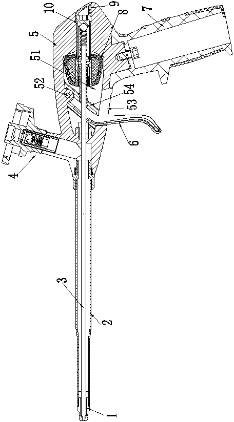
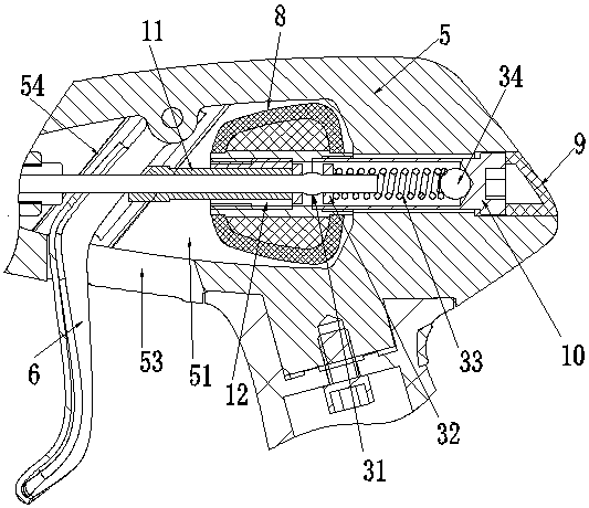
[0031] Combined with the drawings in the description, the foaming gun includes a gun body 5, a gun barrel 2, an adapter 4 and a handle 7. The gun body 5 is made of metal, the gun barrel 2 is connected to the front side of the gun body 5, and the adapter 4 is located on the gun body 5. The upper side of the adapter 4 is used to connect with the foam tank, and there is a passage leading to the gun barrel 2 in the adapter 4 . The gun barrel 2 is coaxially provided with a needle bar 3, the outer end of the gun barrel 2 is provided with a needle cap 1, and the needle cap 1 is provided with a liquid outlet hole, which is determined by the cooperation between the needle bar 3 and the liquid outlet hole. Realize the outflow and cut-off of blowing agent. An adjustment chamber 51 is provided at the middle of the gun body 5 , and an adjustment wheel 8 is rotatably arranged in the adjustment chamber 51 . Described needle bar 3 stretches out from the rear end of gun barrel 2, and stretche...


PUM


Abstract

The invention discloses a foaming gun which solves the problem that a flow regulating structure in an existing foaming gun is relatively complicated and inconvenient to install. The foaming gun structurally comprises a gun body with an adjusting cavity, a gun barrel is connected to the front end of the gun body, and a needle rod is arranged in the gun barrel and extends into the gun body. A trigger connected to the needle bar is hinged to the gun body. An adjustment wheel is rotatably arranged in the adjusting cavity, and the rear side of the adjustment wheel is supported by the gun body. A moving piece is in coaxial and threaded connection with the interior of the adjustment wheel, under the driving of the adjustment wheel, the moving piece slides axially to be used for defining the triggering amplitude of the trigger on the gun body.

Description

technical field [0001] The invention relates to a foaming gun used for spraying foaming agent. Background technique [0002] Foaming agents are often used in architectural decoration. The foaming agent is mainly used to coat the gaps between the boards. The foaming agent left between the boards will seal the gaps between the boards after curing. place. When the foaming agent is sprayed, it is generally realized by means of a foaming gun. The structure of the foaming gun mainly includes a gun body and a gun barrel. A needle bar is arranged in the gun barrel. An adapter and a trigger are arranged on the gun body. The adapter is used to be connected with the foaming tank, and the trigger is connected with the needle bar. When the trigger is pulled, the needle bar will act together with the trigger. After the needle bar moves toward the rear side of the gun body under the drive of the trigger, a gap will be formed between the front end of the needle bar and the needle cap set ...

Claims


Application Information

Patent Timeline
Patent Type & Authority Applications(China)
IPC IPC(8): B05C17/10B05C17/005
CPCB05C17/005B05C17/10
Inventor 梁海军
Owner ZHEJIANG CHAOYU TOOLS CO LTD
Why Eureka
Try Eureka