
Drilling tool penetrating hole puncher
A puncher and drill technology, applied in the direction of metal processing, etc., can solve the problems of not being able to meet the needs of drilling, not being able to complete the drilling, and not being able to complete the drilling action, etc., to achieve good promotion and use value, simple structure , design reasonable effect
- Summary
- Abstract
- Description
- Claims
- Application Information
AI Technical Summary
Problems solved by technology
Method used
Image

Examples
Embodiment Construction
[0047] Below in conjunction with accompanying drawing, the drilling tool piercing device of the present invention is described in detail below.
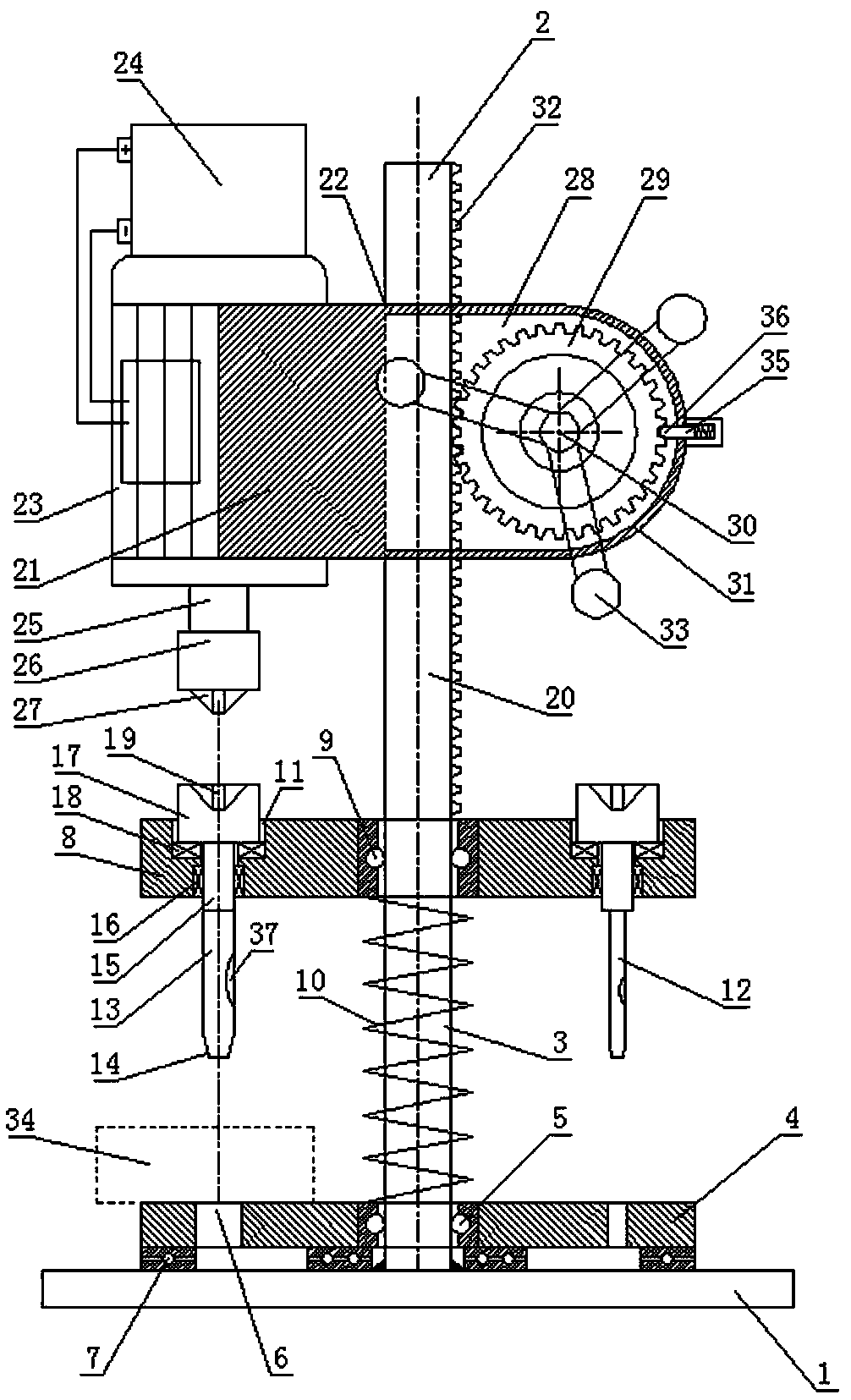
[0048] As shown in the accompanying drawings, the structure of the drilling drill of the present invention includes a base 1 and a support column 2,
[0049] The base 1 is set horizontally, the support column 2 is vertical to the base and fixedly connected to the center of the base, the lower section of the support column 2 is set as a solid cylindrical section 3 with a circular cross section,
[0050] The solid cylindrical section 3 of the support column is pierced with a lower receiving plate 4, and a lower rotating bearing 5 is arranged between the hole wall of the central plate hole of the lower receiving plate 4 and the outer periphery of the solid cylindrical section of the supporting column,
[0051] On the disk surface of the lower receiving plate 4, there are a circle of through holes 6 arranged circularly with the center of...
PUM
 Abstract
Description
Claims
Application Information