
Multi-mold cavity injection mold

An injection mold and multi-cavity technology, applied in the field of multi-cavity injection molds, can solve the problems of increasing the cost of plastic products, insufficient product filling, affecting the quality of plastic products, etc., and achieve the effect of reducing production costs and reducing non-product content.

Inactive Publication Date: 2019-02-22
杭州欣禾工程管理咨询有限公司
View PDF0 Cites 3 Cited by
  • Summary
  • Abstract
  • Description
  • Claims
  • Application Information

AI Technical Summary

Problems solved by technology

[0003] Existing multi-cavity injection molds usually design the raw material flow channel into an "H"-shaped structure, and use the "H"-shaped flow channel to uniformly introduce the raw material from the injection nozzle of the injection machine into each cavity. The front-end melt exerts pressure to make the raw materials continue to be injected into the mold cavity, filling the part of the plastic that has shrunk due to cooling shrinkage to ensure that the product is fully injected. However, this multi-cavity injection mold still has the following problems during injection molding and pressure holding: The molded product of the multi-cavity injection mold includes the part solidified in the gate and the "H" type runner. This part of the molded product does not belong to the product and is often discarded or reused as recycled materials after treatment. Recycled material cannot be used alone as a special raw material for molding. There are strict specifications and restrictions, which increase the cost of plastic product production. When the pressure is maintained, the raw material at the contact between the injection nozzle and the gate gradually solidifies, which makes the injection nozzle clogged and cannot continue to mold the cavity. Feed, resulting in insufficient filling of the product, affecting the quality of plastic production

Method used


Image

  • Multi-mold cavity injection mold
  • Multi-mold cavity injection mold
  • Multi-mold cavity injection mold

Examples


Embodiment Construction

[0024] The following will clearly and completely describe the technical solutions in the embodiments of the present invention with reference to the accompanying drawings in the embodiments of the present invention. Obviously, the described embodiments are only some, not all, embodiments of the present invention.

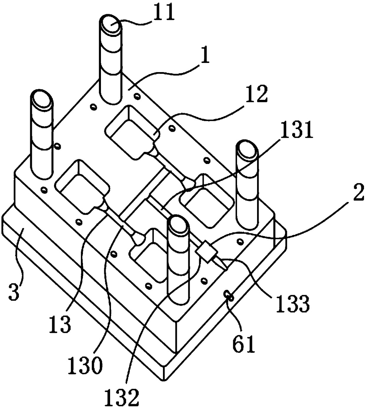
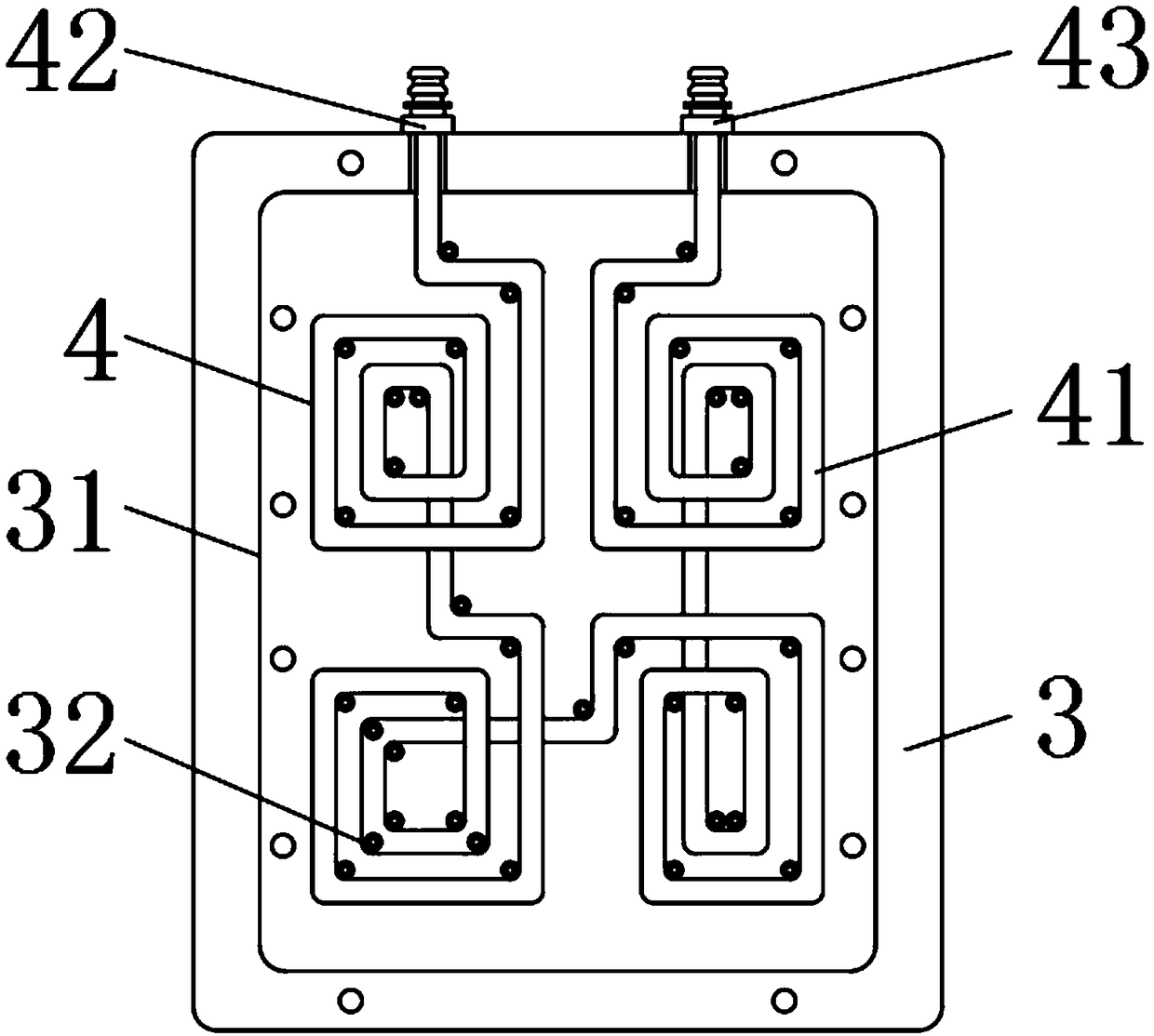
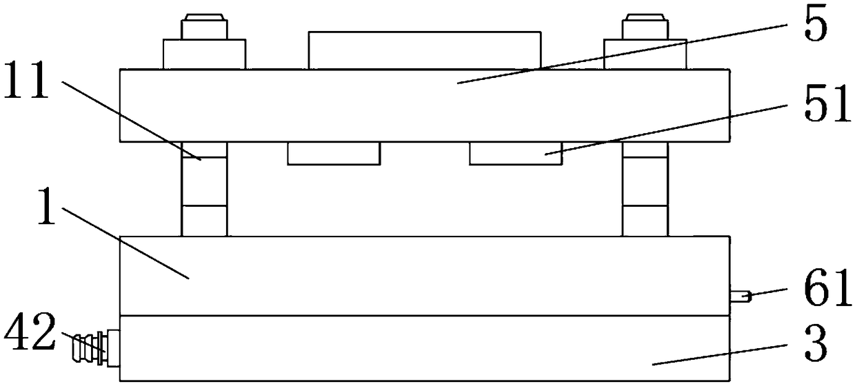
[0025] see Figure 1 to Figure 5, the present invention provides a technical solution: a multi-cavity injection mold, including a lower mold base 1, a pressure maintaining device 2 and an ejection mechanism 6 that are movably installed inside the lower mold base 1, and fixedly installed on the bottom of the lower mold base 1 The cooling base 3, the cooling circuit 4 fixedly installed inside the cooling base 3 and the upper mold base 5 movably installed on the top of the lower mold base 1, the upper surface of the lower mold base 1 is fixedly connected with the guide column 11, the lower mold base 1 The upper surface is provided with four die cavities 12, the upper su...


PUM


Abstract

The invention discloses a multi-mold cavity injection mold, and relates to the technical field of injection molds. The multi-mold cavity injection mold particularly comprises a lower mold base, a pressure maintaining device, an ejection mechanism, a cooling base, a cooling loop and an upper mold base, wherein the pressure maintaining device and the ejection mechanism are movably mounted inside thelower mold base, the cooling base is fixedly mounted on the bottom of the lower mold base, the cooling loop is fixedly mounted inside the cooling base, the upper mold base is movably mounted on the top of the lower mold base, and the upper surface of the lower mold base is fixedly connected with a guide post. The pressure maintaining device is arranged to be used in cooperation with a pressure maintaining cavity, after injection molding is completed, a pressure boosting portion of the pressure maintaining device conducts upward ejection along the pressure maintaining cavity, an injection gateis cut off, a pressure boosting port communicates with a main flow channel, external connection with a pressure pump is carried out in cooperation with a booster pipe, raw materials in an injection molding flow channel are injected into female mold cavities, volume reduction parts caused by cooling shrinkage of plastic is filled up, it is guaranteed that product injection molding is full, no injection nozzle is needed for maintaining the pressure, the raw materials in the injection molding flow channel are effectively used, the non-product content in the molded products of the injection moldis reduced, and the production cost is reduced.

Description

technical field [0001] The invention relates to the technical field of injection molds, in particular to a multi-cavity injection mold. Background technique [0002] Multi-cavity injection mold is a mold with two or more cavities for injection molding production process. Injection molding refers to heating and melting raw materials by injection molding machine and spraying them into the cavity of the mold. After cooling and solidification, the obtained A method of plastic molding. [0003] Existing multi-cavity injection molds usually design the raw material flow channel into an "H"-shaped structure, and use the "H"-shaped flow channel to uniformly introduce the raw material from the injection nozzle of the injection machine into each cavity. The front-end melt exerts pressure to make the raw materials continue to be injected into the mold cavity, filling the part of the plastic that has shrunk due to cooling shrinkage to ensure that the product is fully injected. However, ...

Claims


Application Information

Patent Timeline
Patent Type & Authority Applications(China)
IPC IPC(8): B29C45/26B29C45/40B29C45/73
CPCB29C45/26B29C45/2602B29C45/4005B29C45/7312B29C2045/2651
Inventor 李尚持
Owner 杭州欣禾工程管理咨询有限公司
Learn More