Ceramic-based composite turbine outer ring high-temperature sealing coating and preparation process thereof

A sealing coating, ceramic-based technology, applied in the field of high-temperature sealing coating of ceramic-based composite turbine outer ring and its preparation, can solve problems such as inability to meet high-temperature environment requirements, peeling, etc., to solve the problem of gas corrosion, reduce Fuel consumption, the effect of boosting thrust

Inactive Publication Date: 2019-02-22
SHENYANG LIMING AERO-ENGINE GROUP CORPORATION
View PDF2 Cites 7 Cited by
  • Summary
  • Abstract
  • Description
  • Claims
  • Application Information

AI Technical Summary

Problems solved by technology

In the design of the new engine, SiC / SiC ceramic-based composite materials are used for the outer ring parts of the turbine. The original metal-based high-temperature sealing coating structure system has cracks and peeling phenomena during use, which can no longer meet the requirements of high-temperature environments.

Method used


Image

  • Ceramic-based composite turbine outer ring high-temperature sealing coating and preparation process thereof

Examples


Embodiment 1

[0026] Step 1: Degrease and decontaminate the parts, use alcohol to wipe the sprayed area of ​​the parts to remove oil and sundries;

[0027] Step 2: Protect the parts of the parts that do not need to be sprayed, and use metal tooling to shield them;

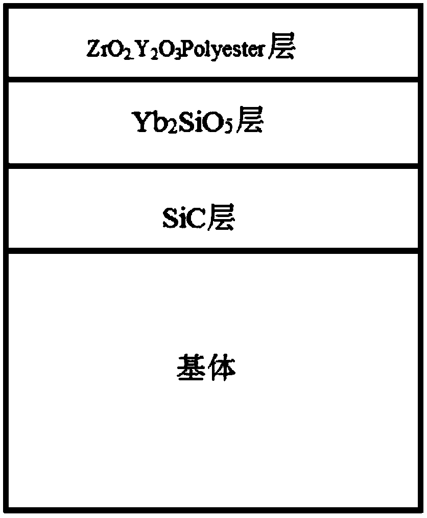
[0028] Step 3: Plasma spray silicon carbide coating on the parts to be sprayed. The specific parameters are current 750A, argon gas flow rate 50L / min, hydrogen gas flow rate 5L / Min, powder feeding rate 20g / min, and spraying distance 110mm. The spraying angle is 90°;

[0029] Step 4: Plasma spray ytterbium silicate coating on the parts to be sprayed. The specific parameters are current 650A, argon gas flow rate 50L / min, hydrogen gas flow rate 9L / Min, powder feeding rate 30g / min, and spraying distance 110mm , the spraying angle is 85°;

[0030] Step 5: Plasma spray yttria-stabilized zirconia + polyester coating on the parts that need to be sprayed. The specific parameters are current 550A, argon flow rate 40L / min, hydrogen flow ...

Embodiment 2

[0034] Step 1: Degrease and decontaminate the parts, use alcohol to wipe the sprayed area of ​​the parts to remove oil and sundries;

[0035] Step 2: Protect the parts of the parts that do not need to be sprayed, and use metal tooling to shield them;

[0036] Step 3: Plasma spray silicon carbide coating on the parts to be sprayed. The specific parameters are current 850A, argon gas flow rate 60L / min, hydrogen gas flow rate 6L / Min, powder feeding rate 30g / min, spraying distance 100mm, The spraying angle is 75°;

[0037] Step 4: Plasma spray ytterbium silicate coating on the parts to be sprayed. The specific parameters are current 750A, argon gas flow rate 60L / min, hydrogen gas flow rate 10L / Min, powder feeding rate 40g / min, and spraying distance 100mm , the spraying angle is 90°;

[0038] Step 5: Plasma spray yttria-stabilized zirconia + polyester coating on the parts to be sprayed. The specific parameters are current 650A, argon flow rate 50L / min, hydrogen flow rate 9L / Min, ...

Embodiment 3

[0041] Step 1: Degrease and decontaminate the parts, use alcohol to wipe the sprayed area of ​​the parts to remove oil and sundries;

[0042] Step 2: Protect the parts of the parts that do not need to be sprayed, and use metal tooling to shield them;

[0043] Step 3: Plasma spray silicon carbide coating on the parts to be sprayed. The specific parameters are current 800A, argon gas flow rate 55L / min, hydrogen gas flow rate 5.5L / Min, powder feeding rate 25g / min, and spraying distance 105mm , the spraying angle is 80°;

[0044]Step 4: Plasma spray ytterbium silicate coating on the parts to be sprayed. The specific parameters are current 700A, argon gas flow rate 55L / min, hydrogen gas flow rate 9.5L / Min, powder feeding rate 35g / min, and spraying distance of 105mm, the spraying angle is 75°;

[0045] Step 5: Plasma spray yttria-stabilized zirconia + polyester coating on the parts to be sprayed. The specific parameters are current 600A, argon flow rate 45L / min, hydrogen flow rate...


PUM

PropertyMeasurementUnit
hardnessaaaaaaaaaa

Abstract

The invention relates to the technical field of aero-engines, in particular to a ceramic-based composite turbine outer ring high-temperature sealing coating and a preparation process thereof. The ceramic-based composite turbine outer ring high-temperature sealing coating comprises a bonding layer, a transition layer and a wearing layer coating from inside to outside in sequence. The bonding layercomprises SiC. The transition layer comprises Yb2SiO5. The wearing layer coating comprises ZrO2.Y2O3Polyester. The coating provided by the invention is a composite coating capable of being matched with a SiC / SiC ceramic-based composite and has the advantages of 1200-DEG C wear consumption sealing and heat insulation. The problems that mechanical damage caused by mutual friction between SiC / SiC ceramic-based composite turbine components, and high-temperature oxidation, structure degradation and other damages to a ceramic-based composite can be solved. The plasma technology has the advantages ofhigh-energy density, high production efficiency, low cost, little equipment investment and the like and belongs to the optimal process for preparing high-temperature-resistant ceramic coating materials.

Description

technical field [0001] The invention relates to the technical field of aero-engines, in particular to a ceramic-based composite material turbine outer ring high-temperature sealing coating and a preparation process thereof. Background technique [0002] During the working process of the engine, under the joint action of centrifugal force, aerodynamic force and thermal expansion, various parts of the rotor and casing will be deformed. Therefore, in the process of design, manufacture and repair, it is necessary to apply an abradable sealing coating on the surface of the outer ring of the turbine to control the gap in the structure, so as to prevent the friction between the tip of the rotating turbine blade and the outer ring of the turbine to cause mechanical damage. damage. Commonly used high-temperature sealing coating materials are generally composed of metallic materials and non-metallic materials, but sealing coating systems based on metallic materials are susceptible to...

Claims


Application Information

Patent Timeline
Patent Type & Authority Applications(China)
IPC IPC(8): C23C4/134C23C4/10C23C4/11C23C4/04C23C4/02
CPCC23C4/02C23C4/04C23C4/10C23C4/11C23C4/134
Inventor 张佳平芦国强张艺馨王璐李浩宇
Owner SHENYANG LIMING AERO-ENGINE GROUP CORPORATION
Why Eureka
Try Eureka