A method and apparatus for temperature control
A control device and positioning technology, applied in the computer field, can solve problems such as equipment downtime, failure to be detected, and burnt out
- Summary
- Abstract
- Description
- Claims
- Application Information
AI Technical Summary
Problems solved by technology
Method used
Image
Examples
Embodiment 1
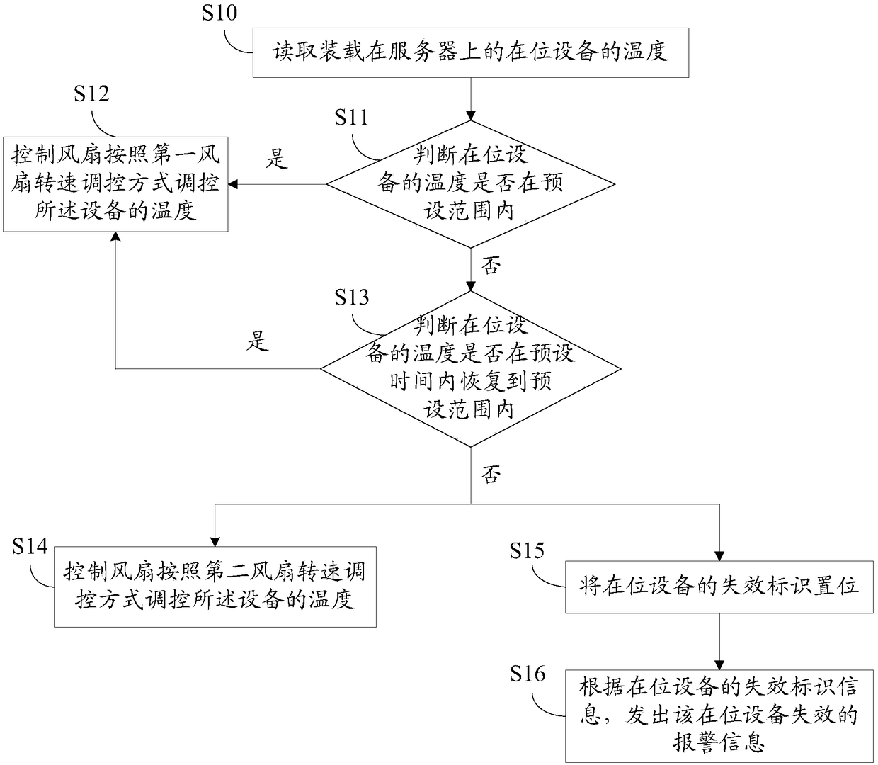
[0044] See figure 1 , the temperature control method provided in the embodiment of the present application, including:
[0045] S10: Read the temperature of the on-site equipment loaded on the server.
[0046] The in-place device refers to the device in the running state on the server after the server is powered on.
[0047] Each device loaded on the server is equipped with a temperature sensor, which can measure the temperature of the on-site device in real time. In this step, the BMC on the server will read the temperature of the temperature sensor on each on-site device in a loop. In this way, the corresponding temperature of each in-position device loaded on the server can be read.
[0048] S11: Determine whether the temperature of the device in place is within a preset range, if yes, execute S12; if not, execute S13.
[0049] Wherein, the preset range may be obtained by performing multiple tests on the device, and the allowable temperature range of the device under the...
Embodiment 2
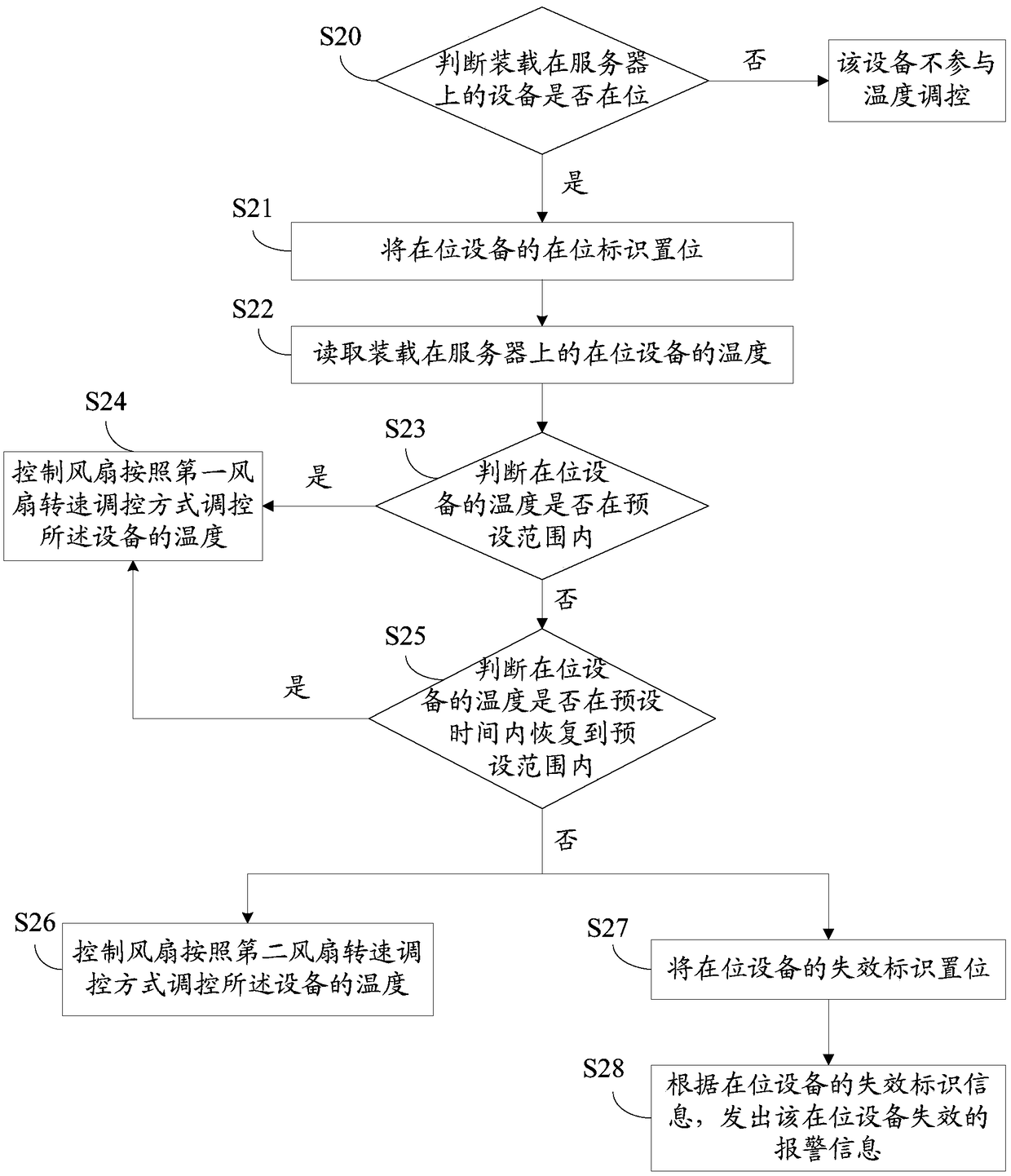
[0069] See figure 2 , another temperature control method provided in the embodiment of the present application, including:
[0070] S20: Determine whether the device loaded on the server is in place, if yes, execute S21; if not, the device does not participate in temperature regulation. ,
[0071] There are many methods for judging whether the device loaded on the server is in place, and in this embodiment of the application, it may specifically include:
[0072] After the server is powered on, read the temperature of the equipment loaded on the server cyclically;
[0073] If the temperature of the device loaded on the server can be read, the device is in place;
[0074] If the temperature of the device loaded on the server cannot be read, the device is not in place.
[0075] It should be noted that, when the device is in place, the device belongs to the target device that needs temperature regulation. Additionally, when equipment is in place, may include:
[0076] S21:...
Embodiment 3
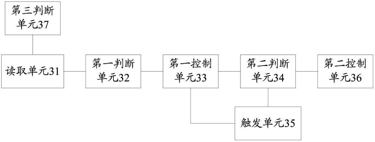
[0083] see image 3 , the temperature control device provided by the application, including:
[0084] The reading unit 31 is used to read the temperature of the on-site equipment loaded on the server;
[0085] A first judging unit 32, configured to judge whether the temperature of the in-position equipment is within a preset range;
[0086] The first control unit 33 is configured to control the fan to regulate the temperature of the device according to the first fan speed regulation method if the temperature of the device in place is within a preset range;
[0087] The second judging unit 34 is used for judging whether the temperature of the on-site equipment returns to the preset range within a preset time if the temperature of the on-site equipment is not within the preset range;
[0088] A trigger unit 35, configured to trigger the first control unit when the temperature of the in-position device returns to a preset range within a preset time;
[0089] The second control...
PUM
 Abstract
Description
Claims
Application Information
 - R&D
- Intellectual Property
- Life Sciences
- Materials
- Tech Scout
- Unparalleled Data Quality
- Higher Quality Content
- 60% Fewer Hallucinations
Browse by: Latest US Patents, China's latest patents, Technical Efficacy Thesaurus, Application Domain, Technology Topic, Popular Technical Reports.
© 2025 PatSnap. All rights reserved.Legal|Privacy policy|Modern Slavery Act Transparency Statement|Sitemap|About US| Contact US: help@patsnap.com


