Method for operating an automatically moving floor treatment device

A technology for processing equipment and ground, applied in the direction of cleaning method using gas flow, automatic control of traveling movement, cleaning equipment, etc., can solve problems such as the existence of dirt

Pending Publication Date: 2019-02-26
VORWERK & CO INTERHOLDING GMBH
View PDF14 Cites 4 Cited by
  • Summary
  • Abstract
  • Description
  • Claims
  • Application Information

AI Technical Summary

Problems solved by technology

[0008] A disadvantage of the methods described is that they carry out the cleaning activity of the cleaning device independently of the cleaning result, so that soiling is always at least partially present after the cleaning operation has ended

Method used


Image

  • Method for operating an automatically moving floor treatment device
  • Method for operating an automatically moving floor treatment device
  • Method for operating an automatically moving floor treatment device

Examples


Embodiment Construction

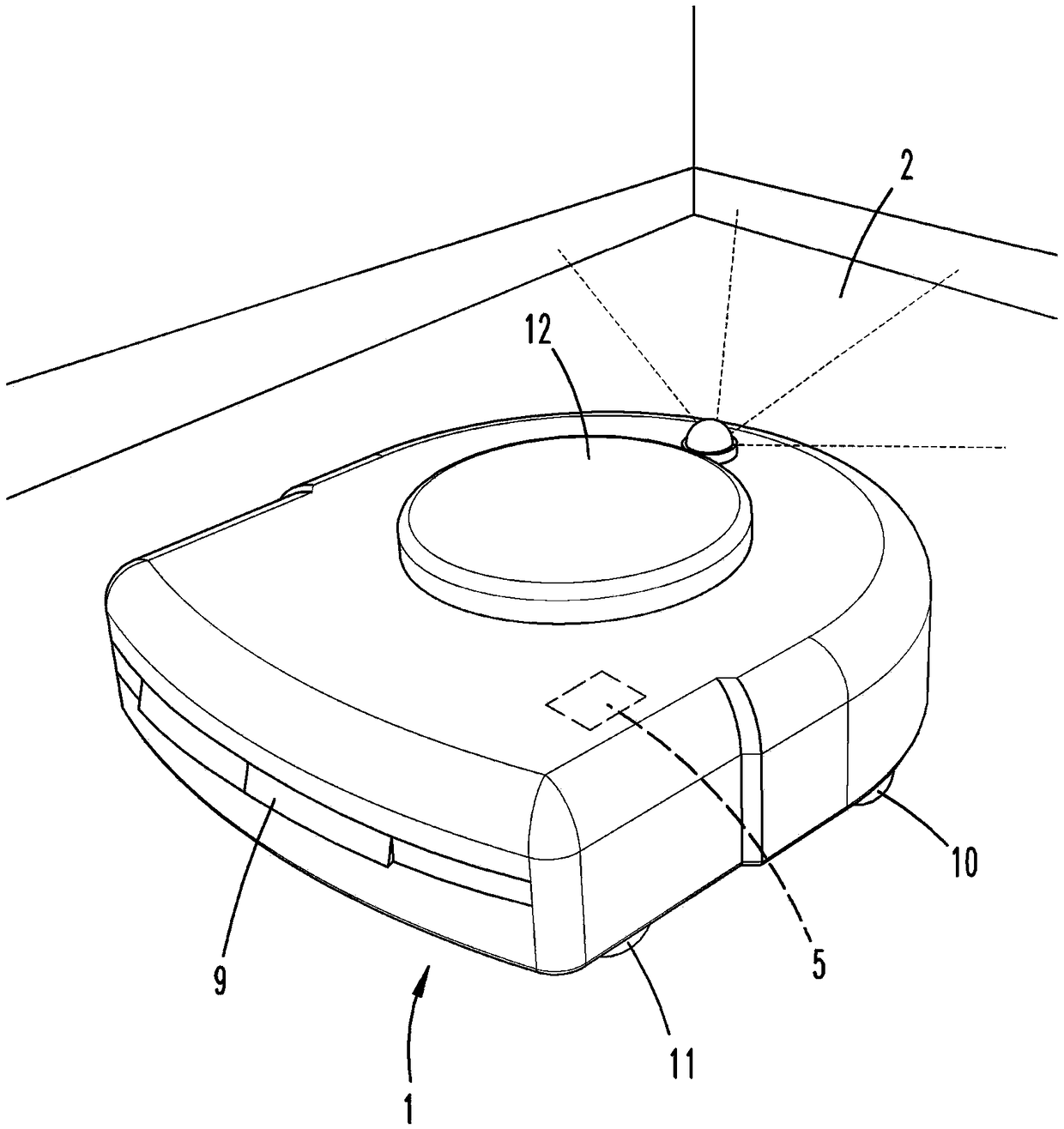
[0030] figure 1 Shown is a floor handling device 1 , which is designed here as a cleaning robot. The ground handling device 1 has motor-driven rollers 10 by means of which the ground handling device 1 can be advanced in the environment. The floor treatment device 1 also has a cleaning element 11, which is also a brush roller which is oriented substantially horizontally in the illustrated normal operating position of the floor treatment device 1 , that is to say substantially parallel to the surface to be treated. Clean flat local area. In the region of the cleaning elements 11 , the floor treatment device 1 has a suction nozzle opening, not further shown, through which air laden with suction material can be sucked into the floor treatment device 1 by means of a motor fan unit. To supply the individual electronic components, for example the drive motor of the roller 10 , the drive motor of the cleaning element 11 and other associated electronics, the floor treatment device 1 ...


PUM


Abstract

A method for operating a floor treatment device (1) that travels autonomously within an environment. The floor treatment device (1) performs a treatment of a defined and spatially limited partial surface region (2) of the environment. During the treatment of the partial surface region (2), a detection device (3) of the floor treatment device (1) measures a treatment status of the partial surface region (2), compares the treatment status with a defined reference status and continues a treatment of the partial surface region (2) until the defined reference status is reached. In order to improvethe result of a floor treatment operation, a user defines the reference status manually and transmits it to the floor treatment device (1).

Description

technical field [0001] The invention relates to a ground-processing device for operating autonomously advancing inside an environment, wherein the ground-processing device performs processing of a spatially defined planar partial area of ​​the environment by definition, wherein during the processing of the planar local area, the ground-processing device The detection device measures the processing state of the planar partial area, wherein the processing state is compared with a defined reference state, and wherein the processing of the planar partial area continues until the defined reference state is reached. [0002] The invention also relates to a floor treatment device that is automatically advanced inside an environment and is designed to carry out the cleaning of a spatially defined, two-dimensional partial area of ​​the environment by definition. Background technique [0003] Ground treatment plants of the kind described above and methods for their operation are known...

Claims


Application Information

Patent Timeline
Patent Type & Authority Applications(China)
IPC IPC(8): A47L11/24A47L11/40
CPCA47L11/24A47L11/40G05D1/0044G05D2201/0203A47L2601/00B08B5/04A47L9/2826A47L9/2857A47L11/4011A47L11/4061A47L2201/04G05D1/0212G05D2201/0215
Inventor M.布雷德P.哈恩L.希伦G.伊森伯格H.温多弗
Owner VORWERK & CO INTERHOLDING GMBH
Why Eureka
Try Eureka