

Fundus examination system
A fundus examination and empty film technology, which is applied in fundus mirrors, eye testing equipment, medical science, etc., can solve the problems of expensive instruments and single functions of instruments.
- Summary
- Abstract
- Description
- Claims
- Application Information
AI Technical Summary
Problems solved by technology
Method used
Image

Examples
Embodiment 1
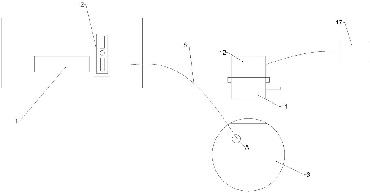
[0035] Such as figure 1 As shown, the fundus examination system of this embodiment includes: a light source 1, a first selection filter device 2 and a light guide device, wherein the first selection filter device 2 is arranged between the light source 1 and the light guide device, and the first selection filter device 2 is arranged between the light source 1 and the light guide device. The filter device 2 allows all the light from the light source 1 to pass through or select the blue light to pass through, and the light guide device is used to guide the light passing through the first selective filter device 2 to the inside of the eyeball 3 .
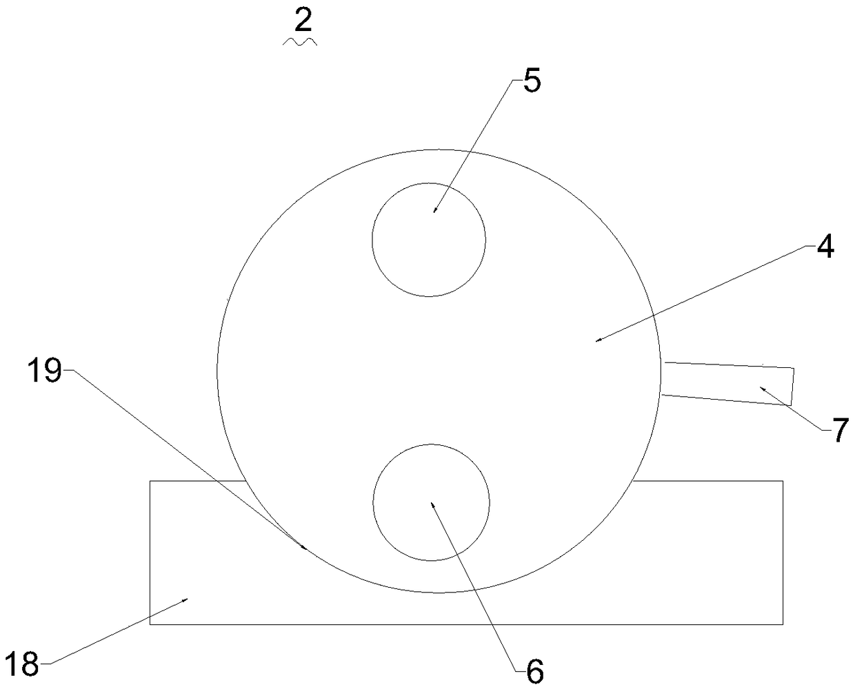
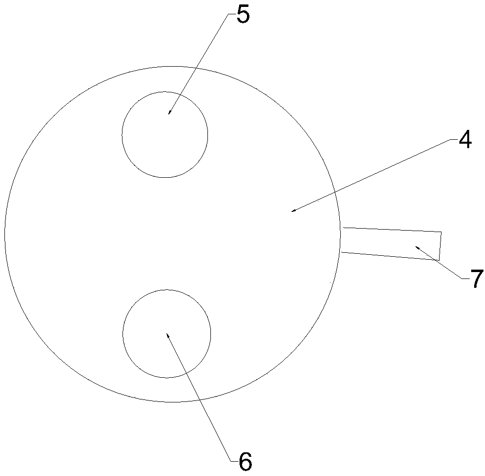
[0036] Such as figure 2 and image 3 As shown, the first selection filter device 2 includes: a first base 18, a first turntable 4, a first blank 5 and a first filter 6, wherein the first turntable 4 is rotatably arranged on the second On a base 18, the first empty sheet 5 allows all the light from the light source 1 to pass through, ...
Embodiment 2
[0042] Such as Figure 7 As shown, the first base 18 is a transparent device, the first turntable 4 is suspended on the first base 18, and the first turntable 4 rotates with the suspension point 23 as the axis, so that the first blank 5 and the first filter The sheet 6 can interchangeably cover the light source 1, a first fixing hole 22 is set on the first turntable 4, a second fixing hole (not shown) is set on the first base 18, the first fixing hole 22 and the second fixing hole allow fixing pieces (not shown) through. The first turntable 4 is rotatable with the suspension point 23 as the axis. The first blank 5 or the first filter 6 can be selected to align with the light source 1. After rotation, the fixing parts pass through the first fixing holes of the first turntable 4 in turn. 22 and the second fixing hole on the first base 18 fix the first turntable 4, therefore, the position of the second fixing hole on the first base 18 is the same as that of the first fixing hole...
Embodiment 3
[0049] Such as Figure 9 As shown, the first selection filter device 2 includes: a first base 18, a first blank 5 and a first filter 6, wherein the first base 18 is provided with a first slot 19, and the first blank The sheet 5 allows all the light from the light source to pass through, the first filter 6 allows the blue light to pass through, and the first empty sheet 5 and the first filter 6 are selectively disposed in the first card slot 19 in a pluggable manner. The first blank 5 and the first optical filter 6 can cover the area of the light source 1 excluding the areas disposed in the first slot 19 . When all the light from the light source 1 needs to pass through, the first blank 5 is selected to be inserted in the first card slot 19. As long as the blue light passes through, the first blank 5 is pulled out, and the first filter 6 is selected to be inserted in the first card slot 19. In slot 19. The first card slot 19 is arc-shaped.
[0050] Such as Figure 10 As s...
PUM
 Abstract
Description
Claims
Application Information