
Integrated test tube cleaning experiment table for teaching

A technology for laboratory benches and test tubes, applied to laboratory stools/lab benches, test tube holders/clamps, cleaning hollow objects, etc., can solve problems such as troublesome operation, time-consuming and laborious, and failure to meet actual use needs, and prevent damage to test tubes , Easy and fast operation, saving drying time

Pending Publication Date: 2019-02-26
大竹县庙坝中学
View PDF0 Cites 4 Cited by
  • Summary
  • Abstract
  • Description
  • Claims
  • Application Information

AI Technical Summary

Problems solved by technology

[0005] The purpose of the present invention is: in order to solve the technical problem that the cleaning of the test tubes in the existing chemical laboratory benches is not only cumbersome, time-consuming and laborious, but the cleaned test tubes need to be dried before they can be put into use and cannot meet the actual use requirements. The present invention provides An integrated test tube cleaning test bench for teaching

Method used


Image

  • Integrated test tube cleaning experiment table for teaching
  • Integrated test tube cleaning experiment table for teaching

Examples


Embodiment 1

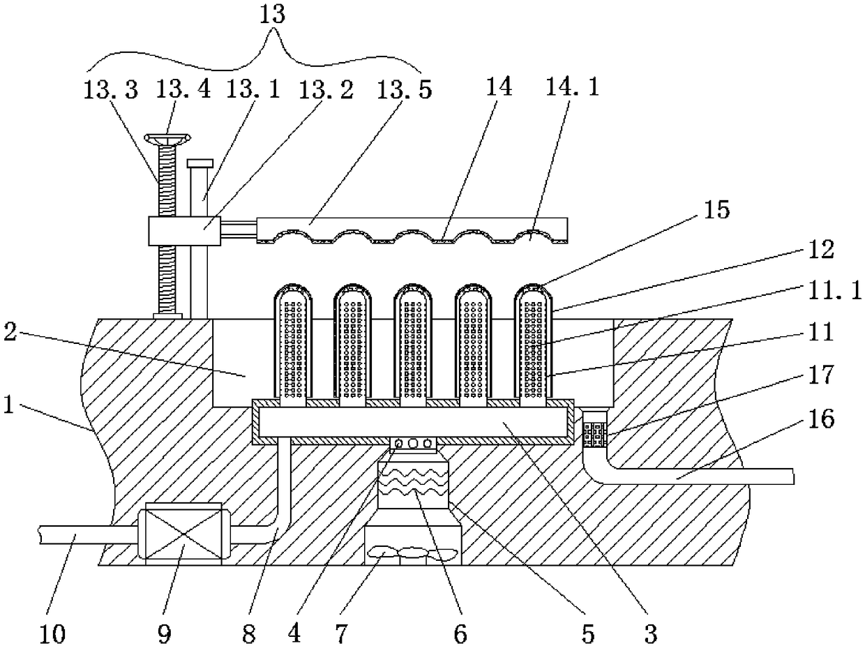
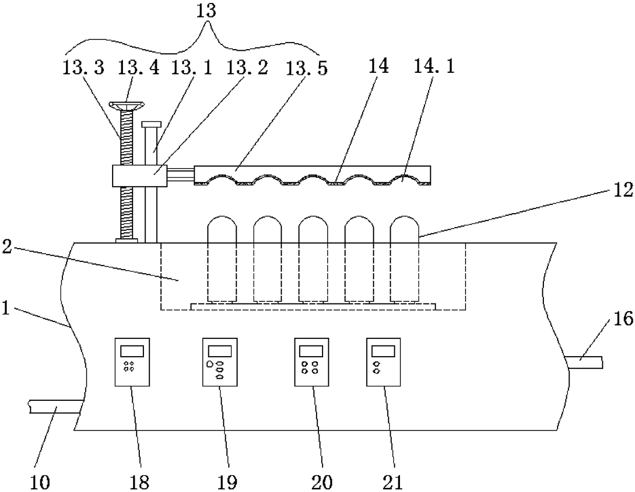
[0027] like Figures 1 to 2 As shown, this embodiment provides an integrated test tube cleaning test bench for teaching, including a cleaning table 1, a cleaning tank 2 is opened on the cleaning table 1, a cavity 3 is arranged at the inner bottom of the cleaning tank 2, and the bottom of the cavity 3 is connected with a The valve 4, the valve 4 is connected with a ventilation pipe 5, the ventilation pipe 5 is provided with an electric heating wire 6, the bottom of the ventilation pipe 5 is connected with a fan 7, the bottom of the cavity 3 is also connected with a first water pipe 8, and the first water pipe 8 is connected with a water pump 9 , the water pump 9 is connected with a second water pipe 10, the top of the cavity 3 is connected with a number of hollow columns 11 that communicate with the cavity 3 for hanging the test tube 12 upside down, and the hollow column 11 is provided with a number of through holes 11.1 communicated with its inner cavity. A limit clamping mech...

Embodiment 2

[0031] like Figures 1 to 2 As shown, this embodiment is further optimized on the basis of Embodiment 1. Specifically, the limit clamping mechanism 13 includes a limit post 13.1 fixed on the cleaning table 1, and the limit post 13.1 is sleeved with a The screw nut seat 13.2 slides up and down, the screw nut seat 13.2 is threadedly connected with a screw rod 13.3, the bottom of the screw rod 13.3 is movably connected to the cleaning table 1 through a ball bearing, the top of the screw rod 13.3 is connected with a rotating handwheel 13.4, the screw nut seat 13.2 passes through Several brackets are connected with a pressure plate 13.5 located above the hollow column 11 for compressing the test tube 12, a layer of rubber pad 14 is arranged at the bottom of the pressure plate 13.5, and the bottom of the rubber pad 14 is provided with a number of arc-shaped grooves 14.1 that cooperate with the corresponding test tubes 12. The top of the column 11 is provided with a soft pad 15 which...

Embodiment 3

[0034] like Figures 1 to 2 As shown, this embodiment is further optimized on the basis of Embodiment 1. Specifically, a drain pipe 16 is arranged at the bottom of the cleaning tank 2 , and an activated carbon adsorption layer 17 is arranged in the drain pipe 16 .

[0035] In this embodiment, the waste water generated in the cleaning process is discharged through the drain pipe, and the activated carbon adsorption layer in the drain pipe has the functions of physical adsorption and chemical adsorption, and has good adsorption performance to avoid chemical pollution.


PUM


Abstract

The invention discloses an integrated test tube cleaning experiment table for teaching and relates to the technical field of teaching equipment. The experiment table comprises a cleaning table, wherein a cleaning tank is formed in the cleaning table, a cavity is formed in the inner bottom of the cleaning tank, the bottom of the cavity is connected with a valve, the valve is connected with a ventilation pipe, an electric heating wire is arranged in the ventilation pipe, the bottom of the ventilation pipe is connected with a fan, the bottom of the cavity is connected with a first water pipe connected with a water pump, the water pump is connected with a second water pipe, a plurality of hollow columns communicated with the cavity and used for hanging test tubes upside down are connected withthe top of the cavity, through holes communicated with the inner cavities of the hollow columns are formed in the hollow columns, and a limit clamping mechanism for tightly pressing the test tubes isarranged in a position, close to the cleaning tank, of the cleaning table. The experiment table has the advantages of being simple in structure, high in practicability and capable of cleaning and drying the test tubes once and shortening reuse time.

Description

technical field [0001] The invention relates to the technical field of teaching equipment, and more particularly relates to an integrated test tube cleaning test table for teaching. Background technique [0002] Middle school science laboratory is the base of quality education and a place for students to carry out practical teaching. In experimental teaching, we should embark on the track of mutual promotion and coordinated development of equipment allocation, management and use. Only by doing a good job in the maintenance and management of facilities and equipment can we ensure the normal development of experimental teaching and actively create a good learning atmosphere for students. Reasonable use of the laboratory for open experimental teaching makes the laboratory truly a paradise for teachers' teaching and students' innovation. Students have a strong curiosity and desire to explore the world around them. They are willing to operate concrete objects. We should improve ...

Claims


Application Information

Patent Timeline
IPC IPC(8): B01L9/02B01L9/06B08B9/08B08B13/00F26B21/00
CPCF26B21/001B01L9/02B01L9/06B08B9/0804B08B13/00
Inventor 朱杰王昇
Owner 大竹县庙坝中学
Learn More