

Ultrasonic bonding jig, ultrasonic bonding method, and bonding structure
A technology for joining fixtures and ultrasonic waves, which can be used in connection components, manufacturing tools, welding equipment, etc., and can solve the problems of decreased bonding strength between electrode laminates and substrates.
- Summary
- Abstract
- Description
- Claims
- Application Information
AI Technical Summary
Problems solved by technology
Method used
Image

Examples
Embodiment approach 1
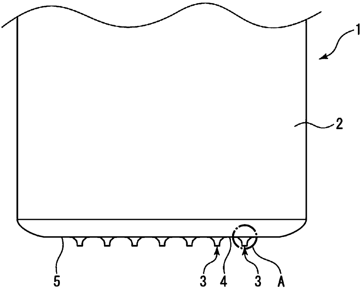
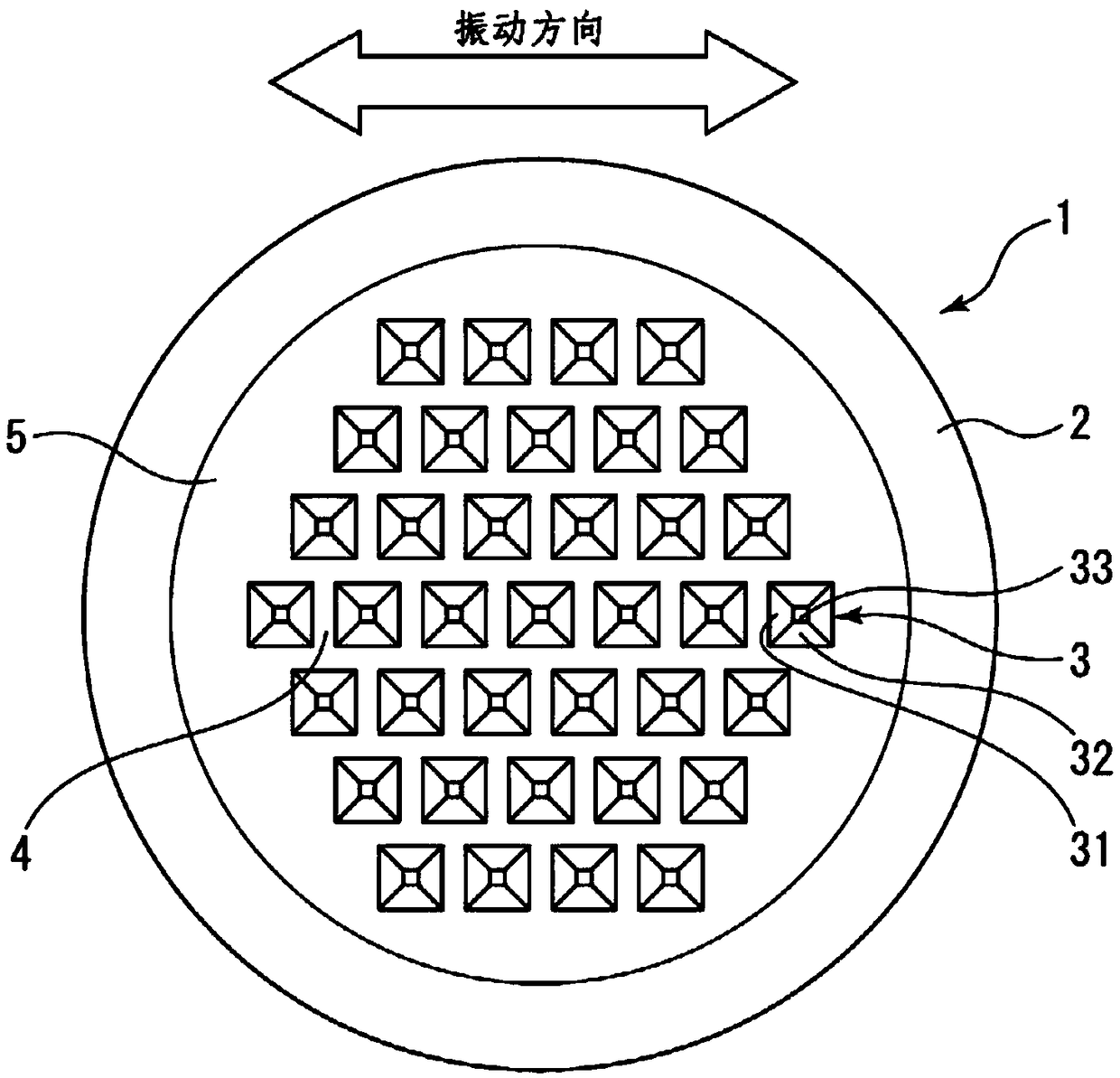
[0065] refer to figure 1 Moving to FIG. 9 , the ultrasonic bonding jig according to Embodiment 1 will be described. Below, will Figure 2A The front side of the paper body and Figure 2B The upper side on the paper is defined as the front side (front side) of the ultrasonic bonding jig. In addition, in the following, up, down, left, and right directions may be referred to as up, down, left, and right directions when the ultrasonic bonding jig is viewed from the front side.
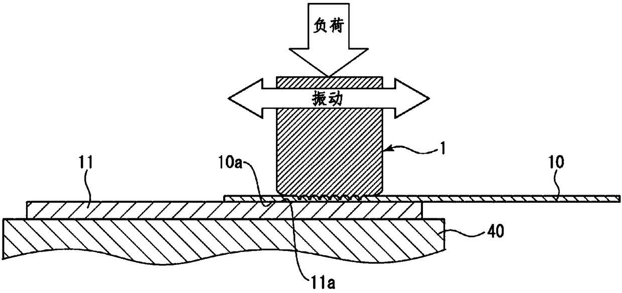
[0066] Such as figure 1 As shown, in ultrasonic bonding, a metal foil 10 (metal plate) made of gold, silver, or copper as a laminate and a metal bus bar 11 (base material) are placed on a support table 40 so as to overlap. . In this state, while pressing the metal foil 10 with the head 1 (ultrasonic bonding jig) attached to the ultrasonic bonding machine, the head 1 is ultrasonically vibrated in the horizontal direction at a predetermined frequency (hereinafter sometimes simply referred to as "vibrati...
Embodiment approach 2
[0091] Next, refer to Figure 10A ~ 10C An ultrasonic bonding jig according to Embodiment 2 will be described. In addition, the same reference numerals are used for the same components as those shown in the above-mentioned embodiment, and overlapping descriptions are omitted.
[0092] Such as Figure 10A As shown, instead of the protrusion 3 of the head 1 shown in the first embodiment, the head (ultrasonic bonding jig) of the second embodiment includes a protrusion 103 . Such as Figure 10A As shown, the protrusion 103 includes a first wall portion 131 (tapered surface), a second wall portion 132 and a protrusion end surface 133 . The first wall portion 131 constitutes a pair of side surfaces arranged to face each other along the vibration direction. The first wall portion 131 is a side surface of the protrusion 103 in the vibration direction. The second wall portion 132 constitutes a pair of side surfaces extending substantially parallel to the vibration direction and ar...
Embodiment approach 3
[0098] Next, refer to Figure 11A and Figure 11B , the ultrasonic bonding jig according to Embodiment 3 will be described. In addition, the same reference numerals are used for the same components as those shown in the above-mentioned embodiment, and overlapping descriptions are omitted.
[0099] Such as Figure 11A and Figure 11B As shown, instead of the protrusion 3 of the head 1 shown in the first embodiment, the head (ultrasonic bonding jig) of the third embodiment has a protrusion 203 . Such as Figure 11A and Figure 11B As shown, the protrusion 203 includes a first wall portion 231 (tapered surface), a second wall portion 232 (tapered surface) and a protrusion end surface 233 . The first wall portion 231 constitutes a pair of side surfaces extending in a direction substantially perpendicular to the vibration direction and arranged to face each other along the vibration direction. The first wall portion 231 is a side surface of the protrusion 203 located in the ...
PUM
 Abstract
Description
Claims
Application Information